Ural vehicles have three independent brakes: a service brake with a hydropneumatic drive on all wheels, a parking brake with a mechanical drive acting on the transmission, and an auxiliary compression type installed on the pipelines of the gas exhaust system
Service brake system
The service braking system is designed to reduce the speed and stop the vehicle regardless of its speed, load and slopes of the roads for which it is intended.
The brake drive is mixed (pneumo-hydraulic), dual-circuit, with separate braking of the wheels of the front and two rear axles.
Control is carried out by a pedal in the driver's cabin, connected by levers and rods with a two-section brake valve.
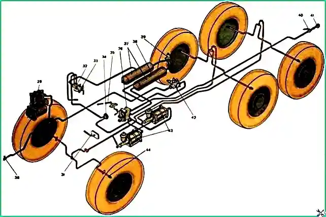
Car service brakes have a hydropneumatic drive, consisting of the following main units: a brake valve compressor, a pressure regulator, two pneumatic boosters with main brake cylinders, an intercylinder reducer of air cylinders, combined using pipelines, hoses and connecting fittings into a single system (Fig. .1).
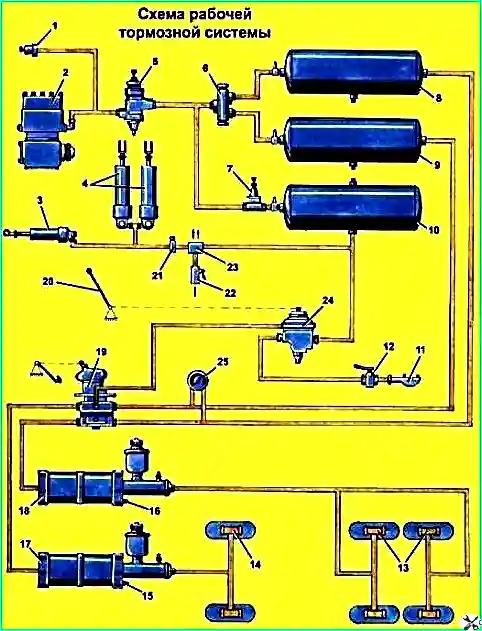
To monitor the car’s service brake units, a two-pointer pressure gauge and a fault alarm system are used.
The lower scale of the pressure gauge shows the air pressure in the area between the air tank and the brake valve, the upper scale shows the air pressure in the air boosters at the moment of braking.
The service brake fault warning system consists of sensors installed in the service brake assemblies (assemblies) and red warning lamps located on the instrument panel.
The “Air” minimum air pressure warning light, when the ignition is on, gives a signal when the pressure in the air cylinder drops to less than 4 kgf/cm 3.
Brake emergency warning light “Brake” turns on when braking with a service brake that has a malfunction or in the mechanical part of the service brake (large gaps between the shoe linings and the brake drum, etc. . etc.), or in the brake hydraulic system as a whole (fluid leakage, air entering the system, etc.).
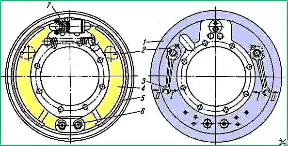
Working brake mechanism: 1 - brake shield; 2 - adjusting eccentric; 3 - key; 4 - brake pad; 5 - friction lining; 6-axis brake pads; 7-wheel cylinder; I - gap reduction; II - increasing the gap
Drum-type working brake mechanism with internal pads 4 (Fig. 2), interchangeable for all wheels.
Each brake mechanism has two hydraulic cylinders 7, made in one housing.
Brake pads are installed on support axles 6.
The working brake mechanism is adjusted as the linings wear by reducing the gap between the lining and the drum using eccentrics 2.
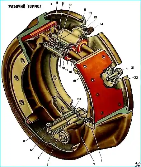
Ural service brake: 1 - drum hatch cover; 2 - brake pads; 3 - pad axle lining; 4 - block bushing; 5 - axes of brake pads; 6 - lock washer; 7 - thrust rod of the block; 8 - thrust piston rod; 9 - wheel cylinder piston; 10 - cuff holder; 11 - brake shield; 12 - wheel cylinder; 13 - bypass valve; 14 - hose; 15 - piston spring; 18 - piston cuff; 17 - wheel cylinder protective valve; 18 - tension spring; 19 - friction linings; 20 - support bracket for pads; 21 - adjusting eccentric bolt; 22 - adjusting eccentric
Brake adjustment procedure:
- - using a 22 mm wrench, turn the adjusting eccentrics of the pads until stop, rotating, right (from the shield side) eccentric clockwise, left - counterclockwise;
- - release the eccentrics by turning them back by about 30°, which corresponds to turning the eccentric axis head halfway.
After performing the above operations on all wheels, check whether the brake drums heat up when the car is moving.
When adjusting the brakes, do not violate the factory settings of the axles 6 brake pads.
Adjust the gaps between the brake pad and the brake drum using the pad axes only when replacing friction linings or pad assemblies.
In this case, initially set the axes of the pads with the marks on the ends facing each other.
Through the hatch in the brake drum, insert a feeler gauge 0.2 mm thick and 200 mm wide between the drum and the shoe at a distance of 30 mm from the bottom edge of the lining.
Turn the axis 6 of the pad and lightly tighten the dipstick.
Remove the feeler gauge, turn the drum and, using another feeler gauge and adjusting eccentric 2, set a gap of 0.35 mm between the block and the drum at a distance of 30 mm from the top edge of the lining.
Secure the axles of the pads and check the gaps between the pad and the drum again.
If the linings are worn down to the plane of the rivet head, replace them.
If the brake linings become oily, wash them with gasoline.
If the brake drum is worn out or there are ring grooves more than 2 mm deep, bore the working surface of the drum along the outer rings of the hub bearings.
The run-out of the working surface of the drum should not exceed 0.25 mm, and the diameter of the drum should not exceed 424.38 mm.
On the front axles of heavy-duty vehicles, only code linings 143-63 (gray) should be installed.
Mixed (pneumohydraulic) drive of service brakes
The vehicle is equipped with a dual-circuit brake drive with a combined trailer drive and additional braking devices.
The drive provides the ability to connect the brake systems of trailed vehicles with single-line or two-line brake actuators.
The schematic diagram of the brake drive is shown in Fig. 4.
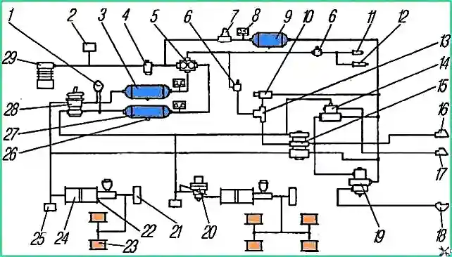
Diagram of the drive of service brakes and the combined drive of trailer brakes: 1 - two-pointer pressure gauge; 2 - towing valve; 3, 9, 27 - air cylinders; 4 - pressure regulator; 5 - triple protective valve; 6 - pneumatic trailer brake release valve; 7 - single protective valve; 8 - pressure drop sensors; 70 - trailer parking brake control valve; 11 - pneumatic fuel shut-off cylinder; 12 - pneumatic cylinder for closing the exhaust flap; 13 - double-line valve; 14 - safety valve; 15 - trailer brake control valve with a two-wire drive; 16, 17 - automatic connecting heads; 18 - connecting head type “A”; 19 - trailer brake control valve with a single-line drive; 20 - brake force regulator; 21 - sensors for turning on the brake signal; 22 - brake fault sensors; 23 - wheel cylinders; 24 - pneumatic brake booster; 25 - control valves; 26 - condensate drain taps; 28 - brake valve; 29 - compressor
Compressor 29 supplies compressed air through pressure regulator 4 to the safety valve block.
The block consists of triple 5 and single 7 safety valves that distribute and fill air cylinders into 3, 9 and 27 independent circuits:
- - front wheel brake drive;
- - drive the brake mechanisms of the middle and rear wheels;
- - combined drive of the brake mechanisms of trailer wheels.
The first main circuit consists of an air cylinder 3, the upper section of the brake valve 28, a pneumatic booster 24 and wheel cylinders 23, and the second main circuit consists of an air cylinder 27, the lower section of the brake valve 28, a brake force regulator 20, a pneumatic booster 24 , wheel cylinders 23.
The third circuit consists of an air cylinder 9, trailer brake control valves: 19 - single-wire bottom drive and 15 - with a two-wire drive, connection head 18 type “A” for connecting trailers with a single-wire drive, automatic connection heads 16, 17 for connecting trailers with a two-wire brake drive.
Air is taken from air cylinders 3, 27 through a triple safety valve 5 to operate the windshield wipers, air signal, pneumatic clutch booster and other consumers.
If it is necessary to control the air pressure, control outlet valves 25 are installed in each circuit, to which a portable pressure gauge can be connected.
When driving a car with a trailer that has a single-wire brake drive, the connection of the car with the trailer is carried out by connecting head 18, two-wire - by connecting heads 16, 17.
When you press the brake pedal, the first and second circuits of the vehicle brake drive are activated, as well as the third circuit of the trailer brake drive.
If one of the circuits fails, the others remain operational.
To brake a car with a trailer in a parking lot, set the parking brake lever to the upper fixed position: in this case, control valve 10 releases compressed air from terminal “II” of valve 15 (see Fig. 4) and activates the brake mechanisms of the trailer.
The car has an alarm system and brake monitoring system. Minimum air pressure sensors are installed in the air cylinders.
The pneumatic boosters are equipped with sensors that indicate a malfunction of the service brake system (brake fluid leakage or large gaps between the pads and the drum).


