Compressor (Fig. 1) piston type, indirect flow, two-cylinder, single-stage compression
Air from the engine air filter enters the compressor cylinders through the vane inlet valves.
The air compressed by the pistons is forced into the pneumatic system through plate discharge valves located in the cylinder head.
The block and head are cooled by liquid supplied from the engine cooling system.
The compressor cooling system is filled only when the engine is running.
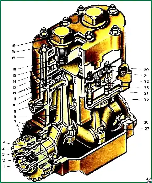
Ural car compressor: 1 - seal, 2 - seal spring, 3 - gear fastening nut, 4 - lock washer, 5 - segment key, 6 - drive gear, 7 - crankshaft, 8 - connecting rod, 9 - oil scraper ring , 10 - piston pins, 11 - pistons, 12 - compression rings, 13 - head gasket, 14 - discharge valve seat, 15 - discharge valve, 16 - discharge valve spring, 17 - cylinder head stud, 18 - cylinder head, 19 - discharge valve plug, 20 - intake valve spring, 21 - intake valve, 22 - rocker arm, 23 - rocker arm spring, 24 - plunger with rod, 25 - cover, 26 - crankcase, 27 - connecting rod bolt
Oil is supplied to the rubbing surfaces of the compressor through a tube from the engine oil line to the rear cover of the compressor crankcase and through the seal through the crankshaft channels to the connecting rod bearings.
Signs of a malfunctioning compressor are noise during operation, knocking, and increased oil content in the condensate drained from the air cylinders.
Increased oil content in the condensate is usually a consequence of wear of the piston rings and bearings of the lower connecting rod heads.
The compressor is installed in the rear part of the engine camber (Fig. 2) and is secured with four bolts 15 to the front wall of the timing gear cover 14, made in the same casting as the flywheel housing.
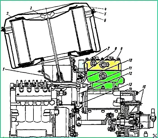
Installing the compressor on the engine: 7 - connecting pipe; 2 - air filter cover; 3 - rod for fastening the filter element; 4 - filter element; 5 - cover seal; 6 - filter housing; 7 - solenoid valve; 8 - fuel line bolt; 9 - compressor; 10 - fuel hose; 11 - union nut; 12 - water supply tube; 13 - nuts; 14 - cover; 15 - bolts
Compressor maintenance
Lap valves that do not provide a tight seal to the seats; if worn or damaged, replace them.
Lap new valves to the seats until continuous annular contact is obtained when checking for paint.
Tighten the nuts of the cylinder head mounting studs in pairs, starting with the middle diametrically located pair.
Tighten the nuts in two steps: the final tightening torque should be 12-16 N.m (1.2-1.6 kgf/m).
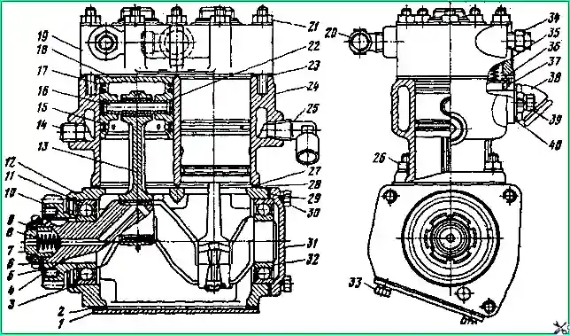
Compressor: 1 - lower crankcase cover; 2, 23, 27, 29 – gaskets; 9, 9, 22 - retaining rings; 4 - crankshaft; 5 - lock washer; 6 - nut; 7 - seal; 8 - spring; 10 - gear; 11, 82 - bearings; 12 - crankcase; 13 - connecting rod; 14 - plug; 15 - oil scraper ring; 16 - piston pin; 17 - compression ring; 18 - piston; 19 - head assembly; 20, 25 - screwed squares; 21, 26 - nuts; 24 - cylinder block; 28 - reflective plate; 30, 33, 39 - bolts; 31 - crankcase cover; 34 - fitting; 35 - intake valve spring; 36 - inlet valve; 37 - intake valve guide; 38 - pipe; 40 - gasket for pipe with strainer
Signs of a compressor malfunction: noise and knocking, increased heating, increased oil content in the condensate, which is usually a consequence of wear on the piston rings and the seal at the rear end of the crankshaft, connecting rod bearings, or tarring of the oil drain pipe from the compressor.
To remove the compressor from the engine, drain 10 liters of coolant from the cooling system through the tap on the heater boiler.
Loosen the hose clamp and disconnect the ejection pipe from the damper.
Remove air filter cover 2, filter element 4 and air filter housing 6.
Unscrew the fuel line bolts and union nuts, disconnect the fuel lines from the solenoid valve 7 and the spark plugs of the electric torch starting device.
Disconnect the wires from the solenoid valve and spark plugs.
Unscrew the bolts and remove the connecting pipe 1 of the intake manifolds together with the solenoid valve.
Close the holes on the air ducts with cardboard or plywood plugs.
Unscrew the two nuts 13 securing the flange of the coolant supply tube to the compressor, then the union nut 11 and remove the tube 12.
Remove the tube flange and rubber O-ring.
Unscrew the union nuts and disconnect from the compressor the pipelines connecting the compressor to the vehicle's pneumatic system and the radiator of the engine cooling system.
Unscrew the four bolts 15 securing the compressor to the timing gear cover 14.
Remove the coupling from pipe 38 (Fig. 3) and move the compressor forward to the fuel pump until gear 10 comes out of the cover, remove the compressor.
Close the hole in the lid with a plug made of plywood or cardboard.
Disassembling the compressor
Bend the tendril of the lock washer 5, unscrew the nut 6 and, using the puller “I 801.02.000”, remove the gear 10 from the shaft 4.
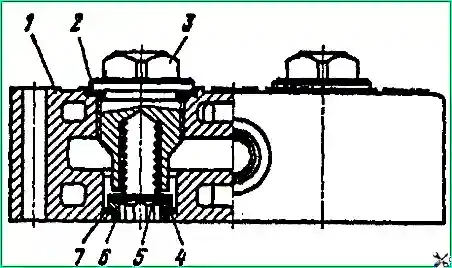
Unscrew the plugs 3 (Fig. 4►) of the discharge valves, remove the springs 5 and valves 4.
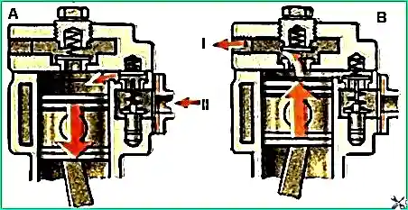
Use a 10x10 square wrench to unscrew seats 6.
Valve plates and seats are ground into each other, so they should not be depersonalized during repairs.
Unscrew bolts 39 (see Fig. 3), remove pipe 38.
Unscrew the nuts 21, protecting the gasket 23 from damage, separate the head 19 from the block 24, remove it and the gasket.
Remove spring 35 and inlet valve 36.
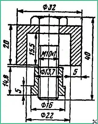
If necessary, use a puller (Fig. 5) to press out the guides 37 of the intake valves (see Fig. 3).
Unscrew bolts 33 and carefully, protecting gasket 2 from damage, remove cover 1 and gasket.
Mark the connecting rods and connecting rod caps and their relative positions.
Unscrew and unscrew the nuts of the connecting rod bolts, remove the connecting rod caps and remove pistons 18 assembled with connecting rods.
Install the connecting rod caps on the connecting rods in the same position and fasten them with connecting rod bolts.
Secure the connecting rod assembly with the piston in a vice, remove the rings from the piston: two compression rings 17 and one oil scraper ring 15.
Remove the lock rings 22 of the piston pin, remove it and disconnect the connecting rod from the piston.
Unscrew the nuts 26 of the studs securing the cylinder block 24 to the crankcase 12.
Remove block 24, reflective plate 28 and sealing gasket 27 from the studs.
Remove retaining ring 9, seal 7 and seal spring 8 from the rear end of the crankshaft.
Unscrew bolts 30 and remove cover 31, gasket 29.
Remove retaining ring 3 from the rear end of the crankcase 12, install the crankcase with its front end on a press and, through a spacer made of “soft” non-ferrous metal, press shaft 4 assembled with bearings 11 and 32 out of the crankcase.
Press the shaft out of the bearings. If necessary, remove the studs from the compressor crankcase.
When repairing the connecting rod and piston group, worn pistons, piston rings and liners must be replaced with repair kits.
The block cylinders and the crankshaft are repaired: the cylinders are bored and honed, the crankpins of the crankshaft are ground to repair dimensions (Table 1).
Table 1.
Compressor crankcase. Diameter of holes for crankshaft bearings:
- - nominal size - 72+0.030 mm;
- - permissible size - 72.05 mm
Cylinder block. Cylinder diameter:
- - nominal size - 60+0.030 mm;
- - permissible size - 60.30 mm;
- - first repair - 60.4+0.030 mm;
- - second repair - 60.8+0.030 mm
Crankshaft. Neck diameter:
- - main bearings - nominal size - 35+0.020 mm; permissible size - 35.00 mm;
- - connecting rod for bearings - nominal size - 28.5-0.021 mm; first repair - 28.2-0.021 mm; second repair - 27.9-0.021;
- - for the drive gear - nominal size - 35+0.020 mm; acceptable - 35.00
Connecting rod assembly with a little eye. Diameter of holes for pin bushing:
- - nominal size - 14+0.019 mm;
- - permissible size - 14.05 mm
Inserts. Wall thickness:
- - nominal size - 1.75-0.013 mm;
- - first repair - 1.90-0.013 mm;
- - second repair - 2.05-0.013
Piston. Outer diameter:
- - heads - nominal size - 59.8-0.095 mm; first repair - 60.2-0.095 mm; second repair - 60.6-0.095 mm;
- - skirts - nominal size - 59.9-0.030 mm; first repair - 60.3-0.030 mm; second repair - 60.7-0.030 mm
Compression ring:
- The gap in the joint when installed in a gauge - nominal size - 0.200-0.400 mm; first repair - 0.200-0.400 mm; second repair - 0.200-0.400 mm;
- Caliber diameter - nominal size - 60,000 mm; first repair - 60,400 mm; second repair - 60,800
Oil scraper ring:
- The gap in the joint when installed in a gauge - nominal size - 0.200-0.400 mm; first repair - 0.200-0.400 mm; second repair - 0.200-0.400 mm;
- Caliber diameter - nominal size - 60.00 mm; first repair - 60,400 mm; second repair - 60,800 mm
When assembling newly installed piston group parts, pistons, connecting rods and pins should be selected according to groups (Table 2).
Table 2.
First group:
- - finger diameter - 12,500-12,497 mm;
- - diameter of the hole in the piston - 12,500-1 2,497 mm;
- - hole diameter in the connecting rod bushing - 12.507-12.504 mm;
- - marking color - White
Second group:
- - finger diameter - 12.497-12.494 mm;
- - diameter of the hole in the piston - 12.497-12.494 mm;
- - hole diameter in the connecting rod bushing - 12.504-12.501 mm;
- - marking color - Green
Third group:
- - finger diameter - 12.494-12.491 mm;
- - diameter of the hole in the piston - 12.494-12.491 mm;
- - hole diameter in the connecting rod bushing - 12.50 1-12.498 mm;
- - marking color - Blue
Fourth group:
- - finger diameter - 12.491-12.488 mm;
- - diameter of the hole in the piston - 12.491-12.488 mm;
- - hole diameter in the connecting rod bushing - 12.498-12.495 mm;
- - marking color - Red
Parts of the first and second repair sizes are marked:
the numbers + 0.4 and + 0.8 are stamped on the bottom of the pistons, the numbers are 0.3 and - 0.6 on the back (steel) side of the liners, one or two stripes wide are applied to the rings on the generatrix with green paint 10 mm.
Before assembling, check the cylinder block and compressor head for tightness with compressed air under a pressure of 15 kgf/cm 2 with immersion in water, for the absence of nicks and warping of the parting planes.
The warpage of the connector planes (0.040 mm) is controlled by a measuring ruler and a feeler gauge.
A 0.05 mm thick probe should not pass under a ruler installed on the connector plane.
Check the connecting rod for bending and twisting using a special device. The non-parallelism of the axes of the upper to the lower (the connecting rod heads is allowed 0.070 mm over a length of 100 mm, their twisting is 0.100 mm over a length of 100 mm.
Assemble the compressor in the reverse order of disassembly. In this case, it is necessary to fulfill a number of the following mandatory requirements:
- - generously lubricate the parts of the connecting rod and piston group with the oil used to lubricate the engine according to the lubrication chart;
- - install the compression rings on the piston with the groove upward (towards the piston bottom).
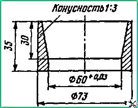
- - before installing the pistons into the cylinder, separate the ring joints at an angle of 120˚. Install the pistons into the cylinder using a mandrel (Fig. 6);
- - the tightening torque of the connecting rod bolt nuts should be 1.5-4.7 kgf/m. It is not allowed to loosen the nut to install the cotter pin;
- - tighten the compressor block head in two steps, the final tightening torque is 1.2-1.7 kgcm;
- - when installing the seal, insert the ends of the spring into the drillings on the crankshaft and seal.
Install the repaired compressor on the car in the reverse order of removal.
We also look at the article about the compressor - “Repairing the compressor of a Kamaz vehicle”


