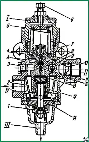
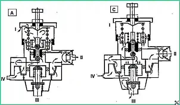
The pressure regulator is designed to regulate the pressure of compressed air supplied from the compressor
Compressed air from the compressor through terminal “IV” (Fig. 1) of the regulator, filter 2, channel 12 is supplied to ring channel 9.
Through check valve 10, compressed air flows to terminal “II” and then into the vehicle’s air cylinders.
At the same time, through channel 8, compressed air passes into cavity “A” under the piston 7, which is loaded by a balancing spring 5. In this case, the outlet valve 4 is open, and the inlet valve 11 is closed.

Under the action of the spring, unloading valve 1 is closed. In this state of the regulator, the vehicle's pneumatic system is filled with compressed air from the compressor.
At a pressure in cavity “A” equal to 800 kPa (8.0 kgf/cm²), piston 7, overcoming the force of spring 5, rises up, valve 4 closes, inlet valve 11 opens and compressed air from cavity “A” enters cavity "B".
Under the influence of compressed air, the unloading piston 13 moves down, valve 1 opens and compressed air from the compressor through terminal “III” escapes into the atmosphere along with the condensate accumulated in the cavity, while the check valve 10 closes.
When the pressure in outlet “II” and cavity “A” drops to 637 kPa (65 kgf/cm²), piston 7 moves downward under the action of spring 5, valve 11 closes, outlet valve 4 communicates cavity “B” with the atmosphere through output "I".
In this case, the unloading piston 13 closes under the action of the spring, and the compressor again pumps compressed air into the pneumatic system.
Unloader valve 1 also serves as a safety valve.
If the regulator does not operate at a pressure of 800 kPa (8.0 kgf/cm²), then when the pressure increases to 1000-1300 kPa (10-13 kgf/cm²) valve 1 opens and the pressure is released.

Adjustment of the regulator is carried out with bolt 6, when tightened, the switching pressure increases, and when unscrewed, it decreases.
The response pressure of the safety valve is regulated by changing the number of gaskets installed under the valve spring.
The correct operation of the pressure regulator is determined by periodic monitoring of the air pressure during engine operation using a two-pointer pressure gauge on the instrument panel and the frequency of operation of the regulator.
During operation, the following malfunctions may occur: wear of the valves, clogging of the throttle hole in the piston.
The regulator is installed on the left side member behind the third cross member of the vehicle frame.
It is more convenient to remove the regulator when the car is installed on an inspection ditch.
To remove the regulator from the car, unscrew the union nuts of the pipelines connecting the regulator to the compressor and air cylinder, unscrew the nut, remove the washer and the regulator assembly.
The pressure regulator must be disassembled and repaired by qualified workers in specialized workshops.
Replace faulty parts during repairs.
If the operating limits of the unloading device or safety valve are violated, they should be adjusted; the pressure at which the compressor regulator begins to disconnect the compressor from the vehicle's pneumatic system is adjusted with a bolt.
You can also see the article “Brake regulator”


