The two-section brake valve (Fig. 1) is designed to control the actuators of the vehicle’s service brake system, as well as to control the trailer brake drive valve
The brake valve consists of an upper and lower body.
The crane lever mechanism is attached to the upper body. The lever body is protected from dirt and moisture by a cover.
The upper cylinder controls the brakes of the trailer (semi-trailer), the lower one controls the brakes of the tractor.
In Fig. 2 - 4 show in detail the device - the covers of the upper and lower cylinders of the brake valve.
The valve is removed from the car and partially or completely disassembled to eliminate air leakage through the outlet due to leaks in valves 15 or cuffs 13 and 19 (see Fig. 1).
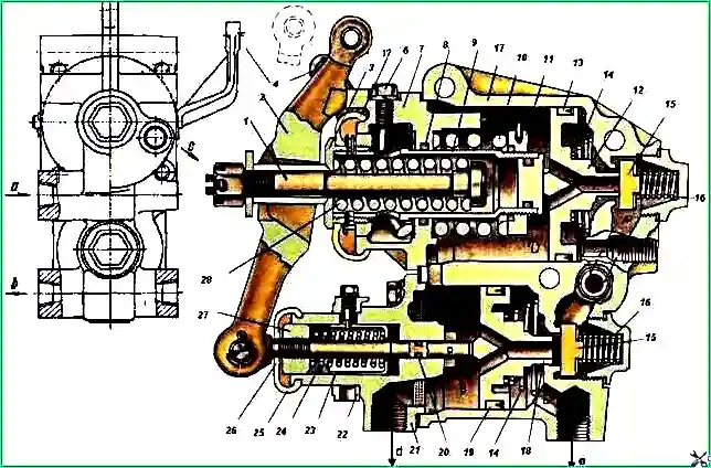
Brake valve: 1 - upper cylinder rod: 2 - lever; 3, 27 - adjusting nuts; 4 - manual drive lever; 5, 25 – dust fuses; 6 - lock bolt; 7- cover of the upper cylinder; 8, 20 - sealing rings; 9 - balancing spring pipe; 10 - balancing spring; 11 - thrust nut; 12- piston of the upper cylinder; 13,19 - piston cuffs, 14 - return springs; 15 - valves; 16 - valve spring; 17 - valve body; 18 - piston of the lower cylinder; 21 - lower cylinder cover; 22 - adjusting mode ring; 23 - adjusting sleeve; 24 - rod spring of the lower cylinder; 26 - thrust of the lower cylinder; 28 - rod spring of the upper cylinder; a - from an air cylinder; b, e - to pneumatic amplifiers; c - into the trailer highway; d - into the atmosphere
The location of the air leak must be determined before removing the valve from the car using the following signs:
- - the leak stopped after turning the parking brake lever 4 - valve 15 of the upper cylinder is leaking;
- - the leak did not stop after turning the parking brake lever - the cuff 13 of the piston of the upper cylinder is leaking;
- - the leak did not stop after pressing the brake pedal - valve 15 or cuff 19 of the lower cylinder piston is leaking.
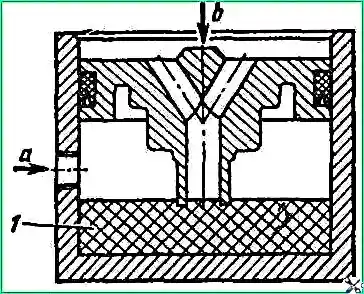
The diagram for checking the tightness of cuffs with pistons is shown in Fig. 5.
The brake valve is installed on a special bracket under the cab and secured with three bolts on the inside of the left frame side member.
When removing the brake valve, unpin the pins of the rods, disconnect the ends of the drive rods from levers 2 and 4 (see Fig. 1) of the brake valve.
Unscrew the union nuts and disconnect the pipelines from the brake valve.
Unscrew the nuts of the valve mounting bolts, remove the washers, brake valve and its bracket from the bolts.
Crane repair
Replace faulty parts during repairs with new, factory-made ones.
When assembling the brake valve after repair, tighten the rod nut 1 so that the free play of the end of the lever 2 is 0.2-4.0 mm, and the working one is 19-21 mm, the free play of the lever 4 is 8-12 mm, and the full — 44-47 mm.
After assembly, check the brake valve and, if necessary, adjust it on a special stand at a constant air pressure of 6.00-6.50 kgf/cm².
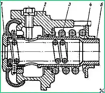
When levers 2 and 4 are in a free position, the air pressure in the trailer brake pneumatic line should be 4.8-5.3 kgf/cm², and there should be no air pressure in the car brake pneumatic line.
Adjustment is made by rotating nut 3, having previously unscrewed the locking bolt 6.
If the air pressure in the brake line is less than 4.8-5.3 kgf/m², nut 3 must be rotated clockwise.
When lever 2 is fully retracted, there should be no air pressure in the trailer pneumatic line; in the car brake pneumatic line, it should be equal to the air pressure in the air cylinder.
Adjustment is made using rod nut 1 within the working stroke of the end of the lever 19-21 mm.
It is necessary to check the adjustments with three fixed positions of the mode ring 22, which must be turned with a key without jamming.
When lever 4 is fully retracted, there should be no air pressure in the pneumatic line of the vehicle brakes, and in the pneumatic line or trailer brakes decrease from 4.8-5.3 kgf/cm² to 0.
When the lever returns to its original position, the air pressure in the trailer pneumatic line should increase to 4.8-5.3 kgf/cm².
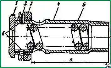
If the air pressure in the pneumatic line of the trailer brakes has not decreased to 0, then it is necessary to adjust the valve by rotating the guide washer 3 (see Fig. 3) relative to the nut 1, reducing the size a, equal to 97.5 mm.
After adjustment, secure the position of the washer relative to nut 1 and pipe 4 with locking ring 2, drilling a new hole in the nut and pipe.
Install the checked and adjusted brake valve on the vehicle, attach the ends of the rods and pipelines.
Check and, if necessary, adjust the brake valve drive.
The maximum air pressure in the pneumatic system after the brake valve (upper scale of the pressure gauge) is regulated by bolt 12 (Fig. 6), which limits the travel of the brake pedal and should be within 4.0-4.5 kgf/cm²
After adjustment, lock the bolt by tightening locknut 11.
Adjust the free play of the brake pedal by changing the length of the rod 16.
It should be within 15-30 mm.
The beginning of the working stroke is determined by a significant increase in the force on the pedal.
In the connection of the lever with the rod there should be a gap between the pin and the bracket of 2 mm, no more. Adjust by changing the rod length.
The brake valve drive (see Fig. 6) is structurally designed together with the clutch control drive and consists of a suspended pedal 5, levers 22 and 24, rods 8 and 16.
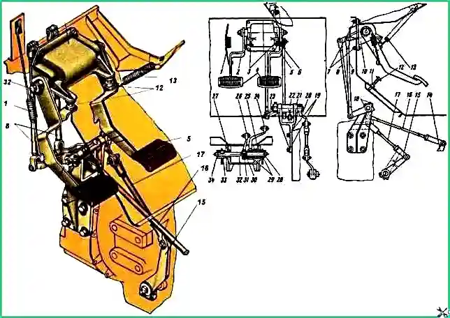
Clutch and brake valve control drive: 1 - clutch pedal spring; 2 - clutch pedal; 3 - adjusting tip; 4 - pedal pad; 5 - brake pedal assembly with shaft; 6 - pedal buffer; 7, 18, 19, 31 - bolts; 8, 9, 16. 17 - thrust; 10 - bracket for clutch and brake pedals; 11 - nut; 12 adjusting bolt; 13 - brake pedal spring; 14 - crane lever; 15 - clutch fork shaft lever; 20, 23 - clutch release shaft levers; 21 - bracket for the clutch release drive shaft; 22 - brake valve control lever; 24 - brake pedal shaft lever; 25, 27, 29 - bushings; 26 - clutch pedal shaft lever; 28, 34 - washers; 30, 33 - keys; 32 - clutch pedal shaft
Removing and disassembling the clutch and brake valve control drive
Disconnect and remove springs 1 and 13.
Unsplit the pins and remove the rods 8, 9, 16 and 17. Unscrew the bolts 7, 19 and remove the assembled brackets 10, 21.
When disassembling bracket 10, unpin the ends of shaft 32 and remove washers 28 and 34.
Unscrew the tightening bolt 31 of the lever 26.
Remove clutch pedal 2 and brake pedal 5, clutch pedal key 33.
Move lever 26 towards the clutch pedal and remove key 30. Remove shaft 32 from the bracket, remove levers 24 and 26.
When disassembling bracket 21, unscrew the tightening bolts 18, remove levers 20 and 23, keys, shaft and lever 22. If necessary, press the bushings out of the levers and brackets.
Data for monitoring the technical condition of brake and clutch drive parts are given in the table.
Table 1.
Clutch pedal shaft. Outer diameter:
- - nominal size - 20-0.020 mm;
- - permissible size - 19.50
Clutch pedal shaft bushing. Inner diameter:
- - nominal size - 20+0.150 mm;
- - permissible size - 20.50 mm
Brake pedal bushing. Inner diameter:
- - nominal size - 32+0.150 mm;
- - permissible size - 32.50 mm
Brake pedal shaft. Outer diameter:
- - nominal size - 32-0.100 mm;
- - permissible size - 31.50 mm
Clutch release drive shaft. Outer diameter:
- - nominal size - 20-0.020 mm;
- - permissible size - 19.50 mm
Brake valve control lever assembly. Diameter of the hole in the bushing for the shaft:
- - nominal size - 20+0.150 mm;
- - permissible size - 20.50 mm
Assembling the brake control drive and carry out the clutch in the reverse order of disassembly.
When assembling, the bushings and shafts must be lubricated with graphite grease.
Connect the brake pedal shaft and lever 24 according to the marks marked on the ends of the splined part of these parts.
Also see the article "Two-section brake valve"
Determination of brake pedal free play
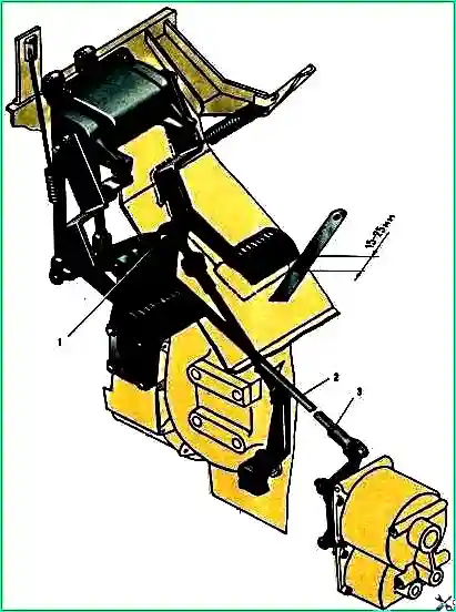
Measure the free play of the brake pedal (Fig. 7). If it is more or less than 15 - 25 mm, adjust it by changing the length of rod 2.
When measuring free play, the drive lever must be pressed against the stop of the upper brake valve cover. The beginning of the working stroke is determined by a significant increase in force.


