The two-section brake valve is designed to control the actuators of the dual-circuit drive of the service brake
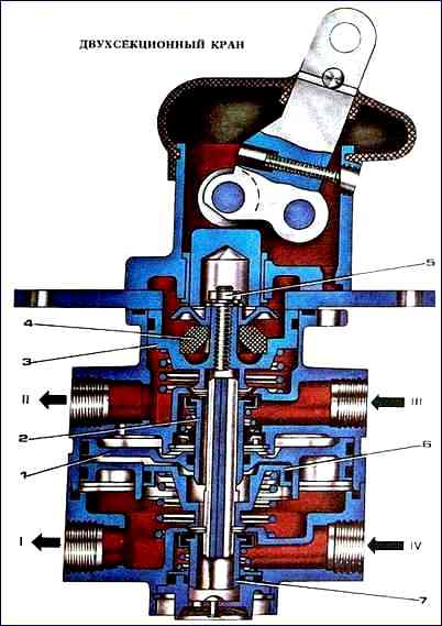
The main elements of the valve (Fig. a) are a large piston 1, upper 2 and lower 11 valves, follower 3 and small 9-stage pistons, elastic element 4, lever 5, pusher 6, pin 7, springs 8 and 10, pusher small piston 12.
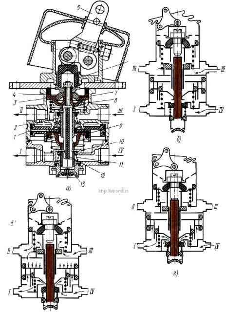
Terminals I and II of the valve are connected through intermediate pneumatic devices to the brake chambers of the front and rear wheels, respectively, terminals III and IV are connected to receivers of separate circuits of the service brake drive.
In the initial position (the brake pedal is released), valves 2 to 11 (Fig. b) are closed under the action of their springs, terminal I is disconnected from terminal IV and terminal II is disconnected from terminal III and they communicate with the atmosphere through valve 13.
When you press the brake pedal (Fig. a), the force is transmitted through the system of drive rods and levers to the brake valve lever 5 and then through the pusher 6 and the elastic element 4 to the follower piston 3.
Moving down, piston 3 compresses spring 8, closes the outlet window when it touches valve 2 and disconnects pin II from the atmosphere, and then lifts valve 2 from the seat.
The compressed air supplied to terminal III, through the open valve 2, flows to terminal II and then through the brake force regulator into the brake chambers of the rear wheels until the force of pressing lever 5 is balanced by the pressure of compressed air and spring 8 on piston 3.
In this way, the tracking action of the piston in the upper section of the brake valve is carried out.
Simultaneously with the increase in pressure in outlet II, compressed air passes through a channel in the valve body into the cavity above the large piston 1 of the second section of the brake valve, piston 1 moves down and acts on the small piston 9 of the second section of the brake valve.
Moving, piston 9 compresses spring 10, closes the outlet window of valve 11 and disconnects terminal I from the atmosphere, and then lifts valve 11 from the seat.
Compressed air supplied to terminal IV flows through open valve 11 to terminal I and then into the brake chambers of the front wheels.
As the pressure in port I increases, the pressure in the cavity under pistons 1 and 9 increases, which balances the force acting on piston 9 from above.
As a result, a pressure corresponding to the force on the brake valve lever is also established in terminal I.
In this way, the following action of the piston is carried out in the lower section of the brake valve.
If the upper section of the brake valve fails (there is no pressure in port II), the lower section is controlled mechanically through pin 7 and pusher 12, fully maintaining its functionality.
In this case, the tracking action is carried out by balancing the force applied to the lever 5 from above, and the pressure of air and spring 10 on the small stepped piston 9 from below.
Failure of the lower section of the valve (no pressure in port I) does not affect the operation of the upper section.
When the force is removed from the brake pedal, the lever 5 of the brake valve under the action of the elastic element 4 returns to its original position.
The follower piston 3 moves upward by the force of the compressed spring 8, valve 2 sits in the seat, and the access of air from the receiver to terminal II is stopped.
As piston 3 moves further upward, the outlet window opens and output II communicates with the atmosphere through valve 13.
The pressure in port II, and consequently in the cavity above the piston space of large piston 1, falls, pistons 1 and 9 move upward under the action of spring 10, valve 9 sits in the seat, and the access of air from the receiver to port I stops.
As pistons 1 and 9 move further upward, the outlet window opens and outlet I communicates with the atmosphere through valve 13.
Replacing a two-section brake valve
The two-section brake valve must be replaced if the following malfunctions occur:
- 1. Faucet leakage. An external sign is air leakage through the atmospheric valve at the attachment points of the housing sections.
- 2. Mechanical damage to the housing, lever, jamming of the pistons, interfering with its normal operation.
Removing the two-section brake valve
- 1. Release the air from the pneumatic reservoirs of the brake systems of the front and rear axles
- 2. Unscrew the union nuts securing the ends of the pneumatic pipelines to the tees and valve adapter 14 (see figure - brake valve drive)
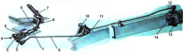
- 3. Unpin and remove the pin connecting the rear link fork 12 of the drive with the crane lever
- 4. Unscrew the nuts of the bolts securing the plate of the upper body of the faucet to the frame brackets and remove the faucet
Installation of a two-section brake valve
- 5. Install the crane on the brackets of the left frame side member and secure with bolts, nuts and spring washers
- 6. Attach the rear link fork 12 of the drive to the lever, insert the pin and pin it
- 7. Connect the ends of the pneumatic pipelines to the tees and the tap adapter, screw and tighten the union nuts
- 8. Start the engine and fill the pneumatic drive of the brake systems with air. Check the tightness of the pipelines and brake valve.
Technical conditions
Air leakage from the atmospheric valve of the valve, both when the brake pedal is released and when the brake pedal is pressed, is not allowed.
Air leakage is not allowed in the pneumatic drive pipeline connections.
- 9. Check and, if necessary, adjust the stroke of the brake valve lever, which should be 31.1 - 39.1 mm, in the following order:
- - unscrew the locknut of the mid-thrust fork a few turns, unscrew and remove the pin connecting the fork with the pendulum lever, remove the fork from the pendulum lever;
- - bring the intermediate lever with the first link to folding and install the required length of the middle link using a threaded fork (by screwing or unscrewing), connect it to the pendulum lever, selecting the gaps in the drive and not allowing forced movement of the brake valve lever. In this case, the full pedal stroke should be 100-140 mm, the free stroke should be 20 - 40 mm.
The pedal should not reach the floor by 10 - 30 mm. Measure at a distance of 210-220 mm from the pedal axis, if necessary, adjust with a threaded fork on the first link.