To adjust (check) the clearances, set the crankshaft to the “I” position corresponding to the start of fuel injection into the 1st cylinder, while turning off the fuel supply by completely repressing the idle speed handle
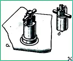
Place the flywheel lock (Fig. 2, a) in the lower position, as shown in Fig. 2, b.
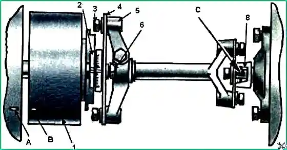
Remove the front hatch cover 1 of the clutch housing (Fig. 5).
Inserting a crowbar into holes 2 on the flywheel, turn the crankshaft as it rotates until the latch, under the action of a spring, engages with the flywheel.
In this case, the position of the marks on the end of the fuel injection advance clutch housing and the flange of the drive coupling half of the high-pressure fuel pump drive (Fig. 3) must coincide and be in the upper position.
If the marks are not in the upper position, disengage the lock and rotate the crankshaft one turn until the crankshaft is locked again.
Install the lock in the upper fixed position.
Rotate the crankshaft in the direction of rotation (counterclockwise, when viewed from the flywheel side) through an angle of 60° (turning the flywheel through the distance between two adjacent holes corresponds to turning the crankshaft by 30°), i.e., to “I” position.
In this position of the crankshaft, the clearance in the valves of cylinders 1 and 5 is checked (the valves are closed, the valve rods can be easily turned by hand).
Check the tightening torque of the nuts securing the rocker arms of the adjustable valves with a torque wrench (Mkr = 4.2 ÷ 5.4 kgcm).
Measure the gap between the toes of the rocker arms and the ends of the valve stems of the 1st and 5th cylinders with a feeler gauge.
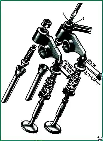
With correctly adjusted gaps, a feeler gauge 0.20 mm thick for the intake valve and 0.30 mm thick for the exhaust valve should fit in freely, a feeler gauge 0.25 mm thick for the intake valve and 0.35 mm thick for the exhaust valve should fit in with force.
If necessary, set the required gap as follows:
- - using a tool for adjusting valves or a wrench and a screwdriver, loosen nut 2 (Fig. 4) of adjusting screw 1;
- - insert the feeler gauge of the required thickness and, turning the screw with a screwdriver, set the required gap;
- - hold the screw with a screwdriver, tighten the nut and check the gap.
The tightening torque of the adjusting screw nut should be 4.2-5.4 kgf-m.
To check the clearances in the remaining valves, install the crankshaft in “II”, “III” and “IV” positions, to do this, rotate it 180°, 260°, 540° respectively relative to the first position of the crankshaft, while checking the valves 4 and 2, 6 and 3, 7 and 8 cylinders.
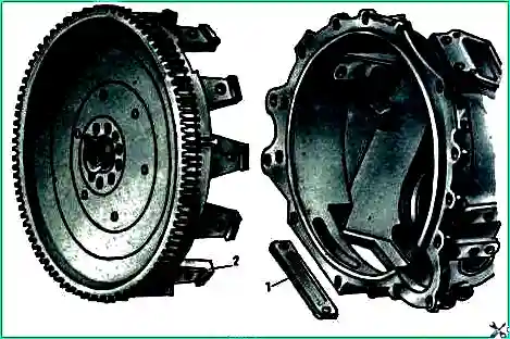
Install the clutch housing hatch covers and cylinder heads in place.
Start the engine. If the clearances are correctly adjusted, there should be no knocking in the gas distribution mechanism.
Checking and tightening the cylinder head bolts
Unscrew the bolts securing the cylinder head covers and remove them.
On a cold engine or no earlier than 30 minutes after stopping it (if it was running), tighten the cylinder head bolts in three steps in the sequence shown in Fig. 1.
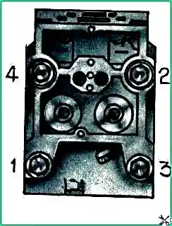
The tightening torque of the bolts should be: in the first step 4-5 kgf m, in the second - 12-15 kgf m, in the third - 19-21 kgf m (limit value).


