The fuel supply system is designed to ensure a supply of fuel in the vehicle, clean it and supply it to the cylinders in strictly dosed portions in accordance with the operating procedure, speed and load conditions of the engine
The power system also includes units for cleaning and supplying air to the cylinders, and a fuel supply control drive.
The diagram of the fuel supply system for the engine of the Ural-4320 and -4420 vehicles is shown in Fig. 1.
On Ural-43202 and -44202 vehicles, an additional fuel tank is not installed in the fuel supply system.
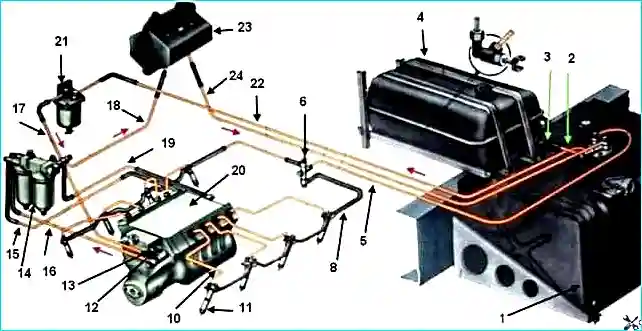
Engine power supply system diagram; 1- main fuel tank; 2 - fuel line from the additional fuel tank to the main one; 3 - tap; 4 - additional fuel tank; 5 - fuel drain line; 6 - tee; 7-pin candle; 8 - fuel drain line of the left row injectors; 9 - Solenoid valve; 10 - high pressure fuel pipe: 11 - injector; 12 - manual fuel priming pump; 13 - low pressure fuel priming pump; 14 - fine fuel filter; 15 - fuel supply line to the high pressure pump; 16 - fuel line to the fine fuel filter; 17 - fuel supply line to the low pressure pump; 18 - drain pipeline from the filter; 19 - fuel drain line of the high pressure pump; 20 - high pressure fuel pump; 21 - fuel coarse filter; 22 - fuel line to the fuel coarse filter; 23 - heater fuel tank; 24 - drain pipe from the heater tank
The main fuel tank is located behind the cabin; it is secured to the left frame side member using clamps and special brackets.
The capacity of the main fuel tank of the Ural-4320 and -43202 vehicles is 210 l, and the Ural-4420 and -44202 - 300 l.
An additional fuel tank with a capacity of 60 liters on Ural-4320 and -4420 vehicles is secured with clamps to the base of the spare wheel holder.
In case of a malfunction (fuel leak), remove the fuel tanks from the vehicle and repair them.
Before removing from the fuel tanks, drain the remaining fuel, disconnect the fuel pipes, and on Ural-4320 and -4420 vehicles, additionally disconnect the sealing system pipes.
On the main fuel tank, disconnect the wire end from the fuel level sensor.
To remove the main and additional fuel tanks, unscrew the nuts of the clamp ends.
When loosening the nuts, keep the ends from turning with an adjustable wrench.
It is more convenient to remove the main fuel tank if the bracket bracket is removed.
Before repairs, rinse the fuel tank inside and out with a 5% caustic soda solution, followed by rinsing with hot water until all traces of fuel are completely removed.
Cracks and holes in the walls of fuel tanks should be repaired by soldering or welding.
Fix large holes by applying sheet steel patches.
The patch should overlap the edges of the hole by 20-25 mm. Thoroughly clean soldering or welding areas with a file, scraper, wire brush or sandpaper to remove paint, rust and dirt.
Before and after repair, check the fuel tank with an air pressure of 0.3 kgf/cm 2 by immersing the area being tested in water.
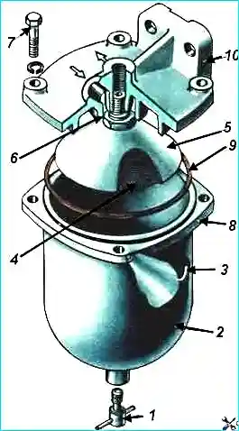
The coarse fuel filter (Fig. 2) is located in the engine compartment and is secured with two bolts to the right side of the hood.
During operation, periodically drain the fuel sediment from the filter through drain plug 1, disassemble and wash the filter parts.
To disassemble the filter, unscrew four bolts 7, remove glass 2, unscrew reflector 5 assembled with filter 4. Wash filter 4 and other parts, and install them in place.
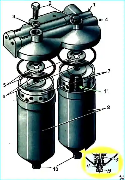
The fine fuel filter (Fig. 3) is mounted on a special bracket to the front of the engine.
A valve is mounted in the filter housing for discharge into the main tank fuel tank excess fuel and air trapped in the system.
To ensure effective collection of air trapped in the system, the filter is located above the other units of the engine fuel supply system.
During the operation of the vehicle, periodically replace the filter elements 7 in the filter and wash the internal cavity of the caps.
To replace the filter elements, unscrew the bolts 2, remove the caps 8, drain the fuel from the caps and remove the filter elements 7.
Rinse the inner cavity of the caps with unleaded gasoline or clean diesel fuel, install new filter elements, gaskets 6 and assemble the filter.
Check the filter for leaks with the engine running. In case of fuel leakage, tighten bolts 2.
If the fuel leak is not eliminated by tightening the bolts, check the condition of the sealing gaskets 5 and washers 3. If damaged, replace them.
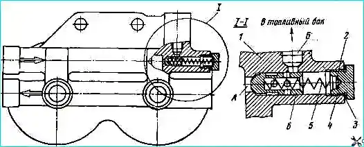
In case of interruptions in the fuel supply to the high-pressure fuel pump, check the operation of valve-nozzle 6 (Fig. 4).
The jet valve transfers fuel and accumulated air from cavity “A” in the filter housing into cavity “B”, connected by fuel pipes to the main fuel tank.
The beginning of fuel flow from cavity “A” to cavity “B” at a pressure in cavity “A” of 1.3-1.7 kgf/cm 2.
If the fuel pressure at the beginning of the flow does not correspond to the above, adjust it by changing the thickness of the washer package 2.
As the thickness of the washer pack increases, the pressure at which fuel begins to flow will increase.
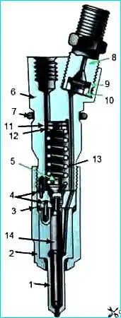
Injectors (Fig. 5) are installed hermetically in special sockets of the cylinder heads and are attached to them with brackets and nuts.
During the operation of the vehicle, periodically remove the injectors for testing and adjustment under bench conditions.
To remove the injectors from the engine, unscrew the nuts and remove the brackets securing the fuel pipes.
Unscrew the union nuts securing the fuel pipes to the injectors and the high-pressure fuel pump and remove them.
Unscrew the fuel line bolts and disconnect the drain pipes from the injectors.
Unscrew the nuts, remove the brackets and remove the injectors from the cylinder head sockets using a puller I-801.11.000.
After disconnecting the fuel lines, the fittings on the high-pressure fuel pump and the removed injectors, as well as the openings of the removed fuel pipes, must be protected from foreign objects and dirt (plugs, caps, plugs, insulating tape).
Disassembly, assembly and adjustment of nozzles should be carried out in a special room on devices and stands under high cleanliness conditions.
When disassembling and assembling injectors, do not touch the working surface of the needle 14 with unprotected hands (see Fig. 5).
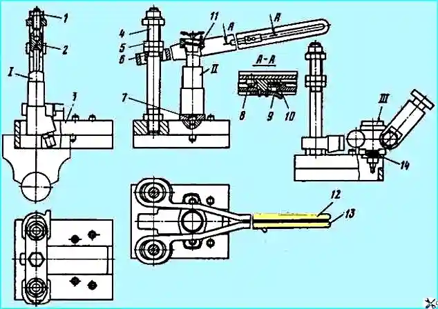
Disassemble and assemble the nozzles using the I-801.20.000 device (Fig. 6), and check and adjust them using devices like KP-1609 or on the KI-3333 stand.
When checking and adjusting, determine the pressure at which the injector needle begins to rise, the quality of fuel atomization and the tightness of the nozzle locking cone.
The pressure at which the needle begins to rise should be 180-185 kgf/cm 2 and adjust it with the thickness of the package of adjusting washers 11 (see Fig. 5).
A change in the thickness of the washer package by 0.05 mm leads to a change in the pressure at which the needle begins to rise by 3.0-3.5 kgf/cm 2.
As the thickness of the pack of adjusting washers increases, the pressure at which the nozzle needle begins to rise increases, with decrease decreases.
The quality of fuel atomization by a nozzle is considered satisfactory if, when fuel is supplied to the nozzle with a frequency of 70-80 swings of the lever per minute, it is injected into the atmosphere in a mist-like state and is evenly distributed over the cross section of the jet cone.
Fuel should be injected from all four injector nozzle holes. The beginning and end of the injection must be clear.
Fuel injection from a new injector is accompanied by a characteristic sharp sound.
The absence of a sharp sound in used injectors is not a disadvantage.
If one or more nozzle holes in the nozzle body are coked, if there is leakage along the needle cone, as well as if it is necessary to adjust the pressure at which the nozzle needle begins to rise, disassemble the nozzle and rinse the nozzle parts in unleaded gasoline or filtered diesel fuel.
Clean the nozzle holes with steel wire with a diameter of 0.25 mm, and clean the outside of the sprayer with a wooden block soaked in engine oil or a brush made of brass wire.
To disassemble the nozzle, it is necessary (see Fig. 5) to unscrew the nut 2, remove the sprayer body 1 together with the needle 14, spacer 3, rod 5, spring 13 and adjusting washers 11.
Unscrew fitting 8, remove sleeve 10 and filter 9. When disassembling, protect needle 14 from accidentally falling out of sprayer body 1.
When disassembling, washing and assembling, protect the nozzle parts from depersonalization.
To do this, rinse and store the parts of only one injector in a separate bath with filtered diesel fuel before assembling.
After rinsing, to protect against damage and depersonalization, needle 14 must be in the sprayer body.
Assemble the nozzle in the reverse order of disassembly. Before assembly, lubricate the injector parts with diesel fuel.
Tighten nut 2 (tightening torque 7-8 kgf/m). After assembly, adjust the nozzle to the pressure at which the spray needle begins to rise and check the quality of fuel atomization.
The atomizer body and needle form a precision pair, in which replacement of any one part is not allowed, therefore, if necessary, they need to be replaced only in pairs.
The newly installed pair (needle and sprayer) must be marked on the sprayer body
Installation of other types of nozzles is not allowed, as this can lead to an increase in smoke and temperature of the exhaust gases, metal burnout on the piston bottoms and cylinder heads, and a decrease in power and economic indicators.


