Engine cooling system - liquid, closed type, with forced circulation of coolant
Main elements of the cooling system: water pump, radiator with curtain, thermostats, fan, fan drive fluid coupling, fluid coupling switch, expansion tank, connecting pipelines.
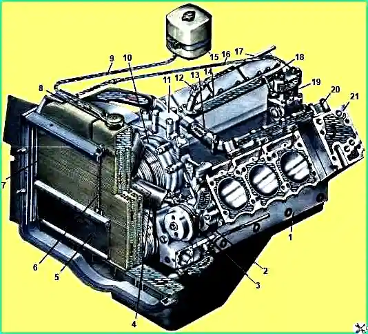
The water pump, thermostats with thermostat box, fan, fan drive fluid coupling, fluid coupling switch are installed on the front of the engine.
The water pump is bolted to the left front of the cylinder block.
To provide access for dismantling the water pump and fluid coupling of the vehicle fan drive, remove the radiator trim, water and oil radiators.
The water pump should be disassembled only when the impeller seal is worn or damaged, as well as when the bearings are worn. Coolant leaking from the pump drain hole indicates wear or damage to the impeller seal.
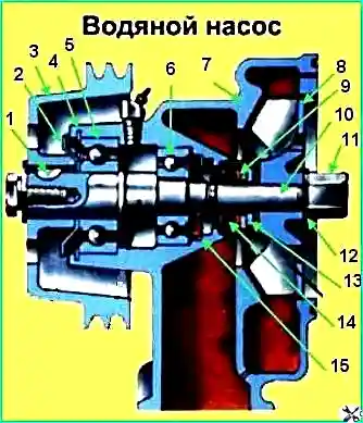
To disassemble the water pump (Fig. 2), press pulley 3 off roller 10, remove key 1 and dust deflector 2;
Remove lock ring 4, unscrew and unscrew nut 11, remove impeller 8, sealing ring 9 and thrust ring 13;
Press out shaft 10, assembled with bearings 5 and 6, from housing 7, press out water deflector 15 and water pump oil seal using mandrels, press bearings 5 and 6 off shaft 10.
Assemble the water pump in the reverse order of disassembly (12 - lock washer, 14 - oil seal).
The fan drive fluid coupling (Fig. 3) and the fan are bolted to the front of the cylinder block.
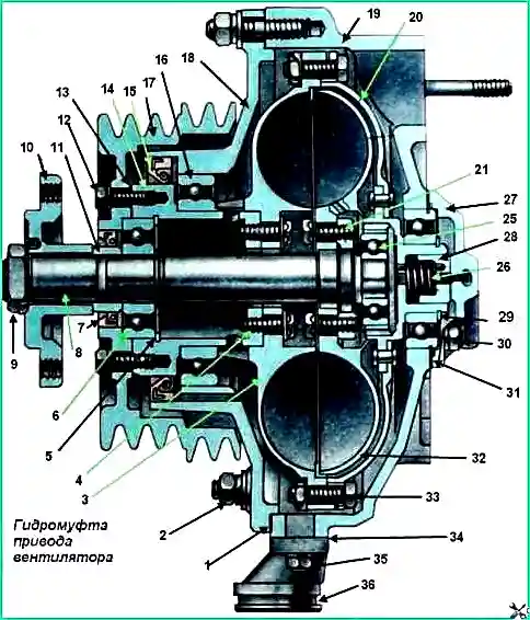
If the rubbing surfaces of the seal 28 and cover 27 wear out, an oil leak will occur and the fluid coupling will not work, i.e., transmit rotation to the fan.
To eliminate this malfunction, remove the fluid coupling from the engine.
Unscrew nuts 30 on the removed hydraulic coupling, carefully remove cover 27 and replace or repair worn parts.
When completely disassembling the hydraulic coupling, undo the cotter pin and unscrew nut 9, remove the washer and compress hub 10.
Unscrew bolts 12, carefully so as not to damage the gasket, separate pulley 17 assembled with cuff 7 from shaft 14.
Remove the pulley, gasket 13 and bushing 11. Unscrew the nuts 30, carefully remove the cover 27, gasket 31, seal 28 and spring 26. Remove the thrust rings 23 and 29.
Unscrew the nuts 2, carefully rocking the housing 18, and remove the hydraulic coupling assembly from the housing-bracket 19.
Unscrew the bolts 33 and disconnect the driven wheel 32 assembled with the shaft 8 and casing 20 from the drive wheel 3.
Remove housing 18 from bearing 16. Using a mandrel, press bearing 6 out of shaft 14, remove thrust ring 5.
In case of emergency (breakage of bearing 16 or wheel 3), unscrew bolts 4, remove washers, press drive wheel 3 and bearing 16 from shaft 14.
Press bearing 24 from drive shaft 22. Using a mandrel, press driven shaft 8 assembled with bearing 25 from drive shaft 22. Press bearing 25 from shaft 8.
In case of emergency, unscrew the bolts 21 and press the shaft 8 out of the driven wheel 32. If the casing 20 or the drive shaft 22 fails, replace them with new ones assembled.
Assemble the coupling in the reverse order of disassembly. At the same time, fulfill a number of requirements.
Before pressing wheel 3 onto shaft 14 and wheel 32 onto shaft 8, the wheels must be heated in an oil bath to a temperature of 100° C.
After assembling the fluid coupling, check the rotation of shafts 14 and 8.
When pressing hub 10 onto shaft 8, use the M8 threaded hole in the front end of the shaft.
Pressing the hub onto the shaft with a hammer is unacceptable, as it may The bearings may be damaged.
When rotating by pulley 17, shaft 14 should rotate freely, without jamming. With pulley 17 stationary, fan hub 10 with shaft 8 should rotate freely, without jamming.
Before installation, lubricate cuffs 7 and 15 with CIATIM-201 lubricant.
Before installation, lubricate gaskets 1, 13 and 31 with grease (34 - gasket, 35 - nut, 36 - drain pipe).
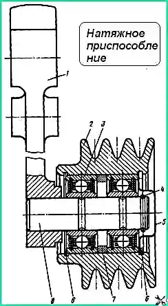
Tensioner (Fig. 4) is used to adjust the tension of the fluid coupling drive belts from the crankshaft pulley.
To remove the tension device, unscrew the nuts of the two studs securing the tension device to the fluid coupling bracket body.
If replacing the pulley bearings, remove the front spring ring 6, cover 5 and locking ring 4.
Remove pulley 2 assembled with bearings 3 from axle 8.
Remove the rear spring ring 6 and press the bearings out of the pulley.
Axle 8 is pressed out of lever 1 only in case of emergency.
Assemble the tension device in the reverse order of disassembly (7 - spacer ring).
The fluid coupling switch (Fig. 5) is installed in the front part of the engine on the pipe supplying coolant to the right bank of cylinders.
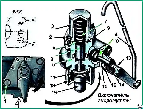
On Ural vehicles, the switch is controlled remotely using rod 4.
In the spring, during seasonal vehicle maintenance, check in bench conditions the response temperature of the fluid coupling switch in automatic mode (lever 13 is set to position B).
If necessary, adjust the switch response temperature by changing the thickness of the package of adjusting washers 17.
To check the operation of the switch in automatic mode, remove it from the engine.
Connect a pipeline with engine oil under pressure of 7 kgf/cm 2 to channel “D”, and lower nut 18 and sensor 19 into a vessel with heated water.
Measure the temperature of the water in the vessel near the sensor with a mercury thermometer with a division value of 1°C. Heat the water in the vessel, stirring constantly.
The switch is adjusted correctly, if at a water temperature of 85-90°C it operates, oil will flow from channel “C.”
If the switch operates at temperatures above 85-90° C, then reduce the thickness of the package of adjusting washers 17.
If the washers cannot be used to adjust the response temperature, replace the sensor.
In case of complete disassembly, unscrew bolts 2, remove cover 3, spring 7, washer 6 and remove spool 8 from body 5.
Unscrew bolts 1, remove cover 16 assembled with plug 11 and lever 13.
Unscrew nut 18, remove sensor 19 and adjusting washers. 17. If necessary, knock out pin 12 and disconnect plug 11 from cover 16 and lever 13, remove spring 14 and retainer 15 (9 and 10 are O-rings).
Thermostats (Fig. 6) are installed in a thermostat box located on the housing-bracket of the fan drive fluid coupling.
To remove the thermostats, unscrew the bolts and remove the cover of the thermostat box.
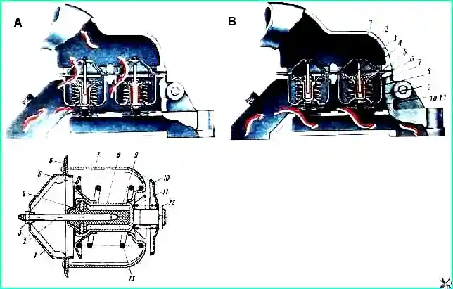
Thermostats control the opening temperature and the full stroke of the valve 10.
The thermostat check diagram is shown in Fig. 7. After heating the water to a temperature of 70° C, carry out further heating with constant stirring.
Take the temperature at which the valve stroke is 0.1 mm as the beginning of valve opening.
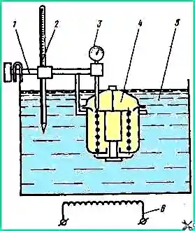
The beginning of valve opening should occur at a temperature of 78–82° C, and full opening should occur at 90–95° C. Full valve stroke 6.8–8.5 mm.
The radiator assembly with fan casing, frame and oil cooler is installed on the first cross member of the frame.
The main malfunctions of the radiator can be: external contamination of the core, damage to the tubes, dents and cracks on the walls of the lower and upper tanks, breakage and cracks of the pipes.
When using water as a coolant, scale deposits may occur.
Before repairs to identify the location of the leak and after repairs to check the tightness, check the radiator with air under pressure of 1.0-1.2 kgf/cm 2 with immersion in a bath of water.
To clean the outer surface of the core from contamination, rinse it with a hot alkaline solution.
Solder damaged outer tubes with soft solder without disassembling the radiator. Internal (not solderable) tubes can be plugged.
The number of plugged tubes should be no more than 5% of the total number of core tubes.
If there are a large number of damaged tubes, as well as to repair the attachment of the pipes to the tanks, open (unsolder) the upper and lower tanks and replace the tubes with new ones.
Straighten the dents in the walls of the tanks, solder the cracks with patches made of sheet brass 1.0-1.2 mm thick.
When using water as a coolant in the spring during seasonal maintenance, flush the cooling system to remove scale.
To do this, pour water into the system with the addition of technical Trilon 20 g per liter of water.
After one day of car operation, drain the solution. Filling with fresh solution daily, flush the system for 4-5 days.
When using low-freezing Tosol-A liquid as a coolant, dilute it with soft, clean water in proportion depending on the ambient temperature in winter.


