During operation of the vehicle, the following malfunctions may occur: incomplete engagement (the clutch slips) or incomplete disengagement (the clutch moves).
If the clutch is not fully engaged with an increase in engine speed, the car either (with the clutch pedal released) does not move away, or its speed increases very slowly
In the cabin you can smell the burnt friction linings of the driven discs.
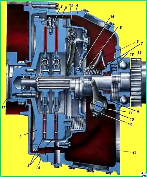
The driven disks slip as a result of:
- no gap between the clutch release bearing and the thrust ring when the clutch pedal is released.
If there is no clearance, the pressure plate is not completely pressed against the driven disk.
To eliminate this malfunction, ensure the clearance between the clutch bearing and the thrust ring by checking and adjusting the free play of the clutch pedal;
- oiling of the clutch discs.
This malfunction occurs as a result of lubricant entering the cavity of the clutch housing through the seals of the input shaft of the gearbox or the rear end of the engine crankshaft, as well as due to excessive lubrication of the clutch release bearing.
The contact of lubricant on the friction surfaces of the discs contributes to their slipping. The clutch must be removed and the discs washed with gasoline;
- wear of the friction linings and friction surfaces of the flywheel of the middle drive and pressure disks. If there is slight wear of the linings, correct the problem by adjusting the free play of the clutch pedal.
If there is increased wear on the linings, flywheel friction surfaces and discs, replace the worn parts;
- shrinkage or breakage of pressure springs. Replace the springs.
When the clutch is not completely disengaged, it is difficult to engage gears, accompanied by impacts of the teeth of the gearbox gears. A malfunction may occur for the following reasons:
- - the presence of a large gap between the clutch release bearing and the thrust ring. This is due to the fact that the clutch release drive does not provide the required travel of the clutch fork shaft lever (reduced full travel, increased free travel of the clutch pedal). The malfunction can be eliminated by checking and adjusting the full or free play of the clutch pedal;
- - skew or warping of the driven disk, unequal gap between the disks due to their warping, and in some places the absence of a gap. This most often occurs when the clutch overheats as a result of slipping. Fix the problem by replacing the damaged disks.
Destruction and breakage of friction linings. Pieces of the lining get stuck between the driven and driving disks and do not allow the lock to be completely turned off. Replace damaged linings;
- skew of the pressure plate. When the clutch is disengaged, the pressure plate continues to press against the driven disk with part of its working surface.
Remove the pressure disk with housing assembly, install it on the device, check and adjust the position of the thrust ring.
Removing the clutch
Remove the gearbox. Screw four tightening bolts into the threaded holes of the pressure plate bosses 12 (Fig. 2).
8 until the bolt heads touch the casing 10. Unscrew the bolts securing the clutch casing and remove the pressure plate 5 (see Fig. 1) assembled with the casing.
Remove driven discs 3 and middle drive disc 2.
Adjusting the position of the clutch thrust ring
Install the pressure plate assembly with the casing on fixture 16 (see Fig. 2) or on the flywheel with an insert that provides an installation dimension “A” equal to 29 ± 0.1 mm.
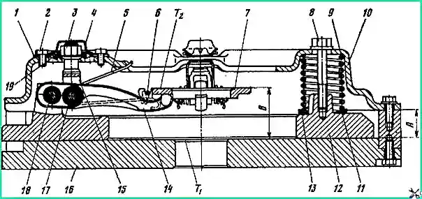
Secure clutch cover 10 with bolts.
Loosen the tightening of the coupling bolts 8 by unscrewing them two or three turns.
Bend the edges of the locking plates 4 and unscrew the bolts 2.
Remove plates 4, 1 and lock washers 19.
Rotate nuts 3 to adjust the position of the thrust ring 7 of the pull-out levers.
Size "B" after adjustment should be equal to 54 ± 0.3 mm, runout of the end T2 of the thrust ring relative to the end T1 - no more than 0.4 mm.
In this case, the supporting surfaces of the ends of all pulling levers 14 must simultaneously touch the thrust ring.
Adjusting the position of the thrust ring after installing the clutch on the engine is prohibited.
After completing the adjustment, install (pre-straightened) lock washers 19. Install support plates 1, plates 4 and secure them with bolts 2.
Bend the ends of the locking plates 4, thereby preventing the bolts 2 from unscrewing. Bend the lock washers 19 through the holes of the plates 4 and 1.
Tighten the coupling bolts 8.
Unscrew the bolts securing the clutch casing and remove the pressure plate assembly with the casing from fixture 16.
Disassembling the pressure disk assembly with casing
Bend the edges of the locking plates 4 and unscrew the bolts 2. Remove the plates 4, 1 and lock washers 19.
Install the pressure plate on the press and tighten the clutch housing 10. Remove the tightening bolts 8 from the threaded holes of the pressure plate bosses.
Unscrew adjusting nuts 3.
Use a press to loosen the pressure springs and remove the clutch cover.
Remove the springs 9 and washers 11 installed on the bosses of the pressure disk together with the thermal insulating pads 13, as well as the thrust ring 7, the lock washers of the axles 18 connecting the pull-out levers 14 with the pressure disk.
Knock out the axles and remove the levers assemblies with forks 15 and springs 5.
Remove the needle bearing rollers from the holes in the levers.
Remove the lock washers of the axles 17 connecting the pull-out levers to the forks 15, and the springs 5 along with the hinges 6.
Knock out axles 17 and remove the forks of the levers. Remove the needle bearing rollers from the holes in the levers.
Disassemble the middle drive disk 2 (see Fig. 1) only if it is necessary to grind the working friction surfaces or to replace parts of the mechanisms for automatically adjusting the position of the disk.
Disassembling the clutch housing
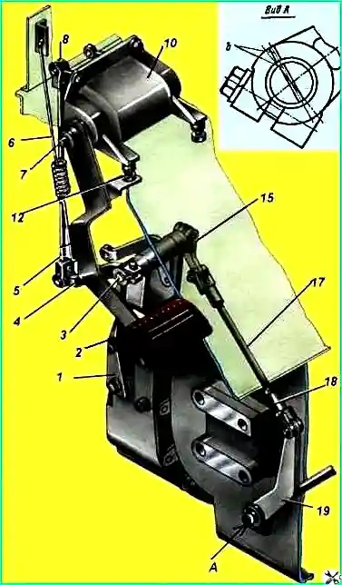
Unscrew the lever pinch bolt 19 (see Fig. 3) and remove the lever from the clutch release fork shaft.
Disconnect hose 6 (see Fig. 1), springs 7 of the clutch release clutch and remove clutch 8 from the guide cover of the gearbox input shaft bearing cover. Remove the oil nipples from the threaded holes of the clutch housing.
Unscrew bolt 12 with a tie and move fork 9 along shaft 11.
Remove the segment key from the groove - the shaft.
Using a copper drift, knock out shaft II of the clutch release fork along with the plug from the holes in the clutch housing.
If it is necessary to replace the bushings, press them out using a mandrel, having first removed the clutch release fork shaft oil seal parts (cover, felt and rubber rings) from the hole in the left crankcase support.
Technical condition monitoring and repair
After disassembling, wash the clutch parts in kerosene, dry them and determine their suitability for further use.
If the fastening of the driven disk hubs or friction linings becomes loose, rivet the rivets or replace them with new ones.
If the driven disk damper springs break or the springs move axially in the disk holes, replace the driven disk assembly.
The following are also subject to replacement:
- - friction linings of driven disks in the presence of large scuffs, peeling or wear to rivets; pressure springs in the presence of cracks and breaks;
- - axles of pull levers having a brinelled working surface;
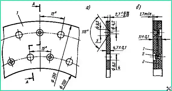
- - worn rollers of needle bearings. The dimensions of the new friction linings and the holes in them for rivets must correspond to those shown in Fig. 4.
When checking the condition of parts, check the change in the elasticity of the clutch release springs.
The force when stretching the spring to a length L = 115 mm must be at least 4.4 kgf.
It is not allowed to operate the middle drive and pressure disks that have through cracks and warping.
At the same time, small thermal cracks on the friction surface of the discs are not a sign for rejection.
Burning, scuffing, non-flatness and uneven wear of the friction surfaces of the middle drive and pressure disks can be eliminated by grinding.
The thickness of the metal removed when grinding the pressure plate should not exceed - 1.3 mm.
The thickness of the middle drive disk after grinding must be at least 23.66 mm.
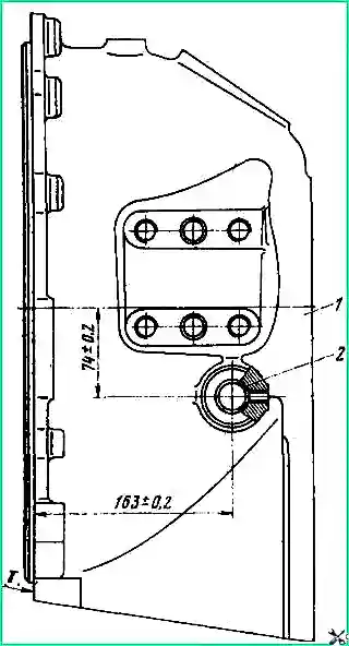
If bushings 2 (Fig. 5) of the clutch release fork shaft are worn beyond the diameter of 25.1 mm, replace the bushings.
Replace bushings using mandrels and a press.
When pressing, point the chamfered ends of the bushings towards each other, and align the holes in the bushings and crankcase supports for lubrication.
Treat the internal surfaces of the pressed bushings in line to a diameter of 25+0.025.
Check the misalignment of the machined bushing holes with a gauge with a diameter of 24.99 mm.
The non-parallelism of the common axis of the bushings and the “T” end should be no more than 0.1 mm over a length of 100 mm.
If replacing the clutch release clutch bearing, press the new bearing until the inner ring stops at the end of the clutch.
Assemble the clutch housing and the middle drive plate in the reverse order of disassembly.
When assembling the middle drive disk, apply Litol-24 lubricant to the rubbing surfaces of the axles and bushings of the release levers. After tightening the axles of the release levers, bend the lock washers on both sides.
After assembly, check the operation of the mechanisms for automatically adjusting the position of the middle drive disk.
When installing a disk on a plate using release levers, the springs should not twist under the weight of the disk and should return the disk to its original position after pressing it until it comes into contact with the plate.
When installing lever 19 (see Fig. 3) on the splines of the clutch release fork shaft, make sure that the marked tooth of the lever fits into the marked cavity of the shaft (marks b).
Assembling the pressure plate with casing
Before assembly, parts must be dry and clean.
When assembling, lubricate the spherical friction surfaces of the adjusting nuts 3 (see Fig. 2), the clutch housing 10, the release levers 14 and the working grooves of the thrust ring 7, as well as the rollers of the needle bearings with Litol-24 lubricant.
When assembling the pressure plate and adjusting the position of the thrust ring of the pull-out levers, ensure that the working surfaces of fixture 16 are clean.
It is unacceptable for dirt and metal shavings to get on the friction surface of the pressure plate and the clutch housing flange.
Assemble the pressure plate in the following order.
Install 20 rollers of the needle bearing of axle 17 into the hole of the pull-out lever 14.
To facilitate the assembly of the needle bearing, apply a thin layer of Litol-24 lubricant to the wall of the hole in the pull-out lever and install six to eight rollers in the hole.
Then insert a split textolite bushing into the hole in the lever (Fig. 6) and install the remaining rollers.
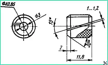
When installing a new needle bearing, assemble it from rollers of the same size group.
Aligning the holes of fork 15 (see Fig. 2) and lever 14, insert axle 17, pushing out the split bushing from the holes of the lever and fork.
In the same way, using a split bushing, assemble the second needle bearing and install the pull-out lever in the groove of the pressure disk boss.
Aligning the hole in the lever with the holes in the boss, insert axle 18, pushing the split bushing out of the holes in the lever and boss.
Install lock washers into the annular grooves of axle 18.
Install spring 5 together with loop 6 on axle 17, and lock washers in the annular grooves of the axle.
In the same way, install and secure the remaining pull-out levers and thrust ring springs. Install and secure the thrust ring 7 with loops 6.
Install the assembled pressure disk onto fixture 16 or a flywheel with an insert that provides an installation dimension “A” equal to 29 ± 0.1 mm.
Install washers 11 together with thermal insulating pads 13 and pressure springs 9 on the bosses of the pressure disk.
If the working surface of the pressure disk has been ground, then to maintain the total force of the pressure springs, place metal washers under the thermal insulating pads.
The thickness of the washers should be equal to the thickness of the metal disk removed during the grinding process.
Install the clutch cover onto the pressure springs. Ensure the vertical position of the forks of the 15 release levers and use a press to compress the springs.
Secure the clutch cover with bolts. As a means of ensuring the vertical position of the forks of the release levers, tubes installed through the holes of the clutch casing on the threaded ends of the forks can be used.
Tighten the nuts 3 and use them to adjust the position of the thrust ring 7 of the pull-out levers.
After completing the adjustment, install (pre-straightened) lock washers 19. Install support plates 1, plates 4 and secure them with bolts 2.
Bend the ends of the locking plates on the edge of the fastening bolts. Bend lock washers 19 through the holes of plates 4 and 1.
In the threaded holes of the pressure plate bosses, screw four coupling bolts 8. Unscrew the bolts securing the clutch housing and remove the pressure disk assembly with the housing from the device.
Installing the clutch on the engine
Before installing the clutch, place 15 g of lubricant 158 into the cavity of the rear end of the crankshaft (under the front bearing of the gearbox input shaft).
Use a clean cloth slightly moistened with gasoline to wipe the friction surfaces of the flywheel, middle drive and pressure plates.
Install driven disk 3 in the flywheel (see Fig. 1) so that the longer part of the disk hub is directed towards the engine.
Apply Litol-24 lubricant to the working friction surfaces of the release levers of the middle drive disk 2 and insert the disk into the flywheel. In this case, the disc spikes should fit into the grooves of the flywheel.
When you press the disk, it should move easily in the grooves of the flywheel and return to its original position under the action of the release levers.
Install the second driven disk 3, positioning the long part of the disk hub away from the engine.
Center the driven disks relative to the axis of the engine crankshaft using a splined mandrel, inserting its end into the hole in the front bearing of the gearbox input shaft.
Install the pressure plate assembly with the housing and secure the clutch housing with bolts. Having secured the casing, unscrew the four tightening bolts.
Install and secure the gearbox.
Check the quality of installation of the clutch and gearbox with the engine running at a crankshaft speed of 1800-2000 rpm by checking:
- - no jamming of clutch release mechanism (drive) parts;
- - the purity of the clutch disengaging when the pedal is fully pressed. In this position of the clutch pedal, the engagement of "I" gear and reverse gear should be done without grinding, and when the "IV" gear is engaged, there should be no rotation of the secondary shaft.
Adjusting the full and free travel of the clutch pedal. The full travel of pedal 2 (Fig. 3), which should be 195 mm, can be adjusted using limiter 12.
To adjust the free play of the clutch pedal, disconnect the linkage 17 from the lever 19. Loosen the locknut of the linkage fork.
By rotating the fork in the required direction, change the length of the rod 17 to increase or decrease the gap between the ends of the thrust ring and the clutch release bearing.
Connect the rod with lever 19 and check the amount of free play of the clutch pedal. If it corresponds to 30-40 mm, tighten the fork locknut.
It is allowed to move lever 19 to one shaft spline (relative to the marks "b" located at the ends of the shaft and lever), if the threads of rod 17 are completely used during adjustment.
Also see the article “Clutch of a KamAZ vehicle", since the clutch is basically the same.


