The high-pressure fuel pump (Fig. 1 and 2) assembled with the injection advance clutch and fuel priming pump is located in the camber of the cylinder block and is secured to the block with four bolts.
The pump is driven from the distribution gears by driven and driven coupling halves.
Pump rotation on the drive side is right (clockwise).
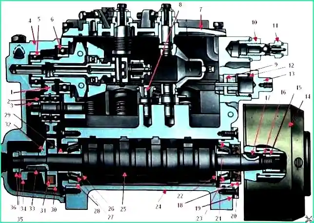
Longitudinal section of the high pressure fuel pump: 1 - intermediate gear of the regulator; 2, 6 - ball bearings; 3, 36 - nuts; 4 - rear cover of the regulator; 7 - top cover of the regulator; 8 - axis of the rack lever; 9 - rack bushing; 10 - pump housing screw; 11 - bypass valve; 12, 21 - sealing rings; 13 - rack plug; 14 - fuel injection advance clutch; 15 - ring nut; 16, 22, 26 - washers; 11, 33 - keys; 18 - front bearing cover; 19 - adjusting shims; 20 - cuff; 23, 27 - tapered roller bearings; 24 - body; 25 - cam shaft; 28 - rear bearing cover; 29 - thrust bushing of the drive gear; 30 - regulator drive gear; 31 - cracker; 32 – flange; 34 - fuel pump eccentric; 35 - lock washer
During the operation of the vehicle, periodically remove the high-pressure fuel pump from the engine for inspection and adjustment on the stand.
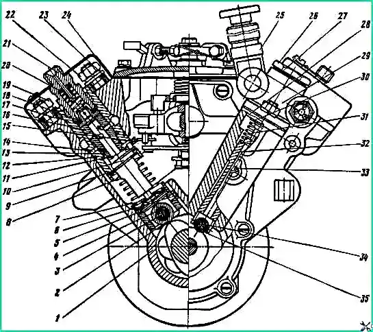
Cross-section of a high-pressure fuel pump: 1 - housing; 2 - pusher roller; 3 - roller axis; 4 - roller bushing; 5 - pusher heel; 6 - cracker; 7 - pusher spring plate; 8 - pusher spring; 9 - washer; 10 - rotary sleeve; 11 - plunger; 12,13 - sealing rings; 14 - mounting pin; 15 - right rail; 16 - plunger bushing; 11 - section body; 18 - gaskets of the discharge casing; 19.22 nuts; 20 - pressure valve spring stop; 21 - fitting; 23 - section housing flange; 24 - protective casing; 25 - manual fuel priming pump; 26 - spring plug; 27 - gasket; 28 - low pressure pump housing; 29 - low pressure fuel priming pump; 30 - rod bushing; 31 - pusher spring; 32 - pusher; 33 - locking screw; 34 - roller axis; 36 - pusher roller
To remove the high pressure fuel pump from the engine, remove the air filter cover, unscrew the rod and remove the filter element.
Loosen the clamps on the air filter housing pipes and remove it.
Unscrew the fuel line bolts and disconnect the fuel hoses from the solenoid valve.
Disconnect the wire going to the solenoid valve from the plug connector.
Unscrew the four bolts and remove the connecting pipe of the intake manifolds and its gaskets.
Close the holes in the intake manifolds with plugs made of plywood or cardboard.
Unscrew the union nuts connecting the high-pressure pipes to the high-pressure fuel pump and injectors. Unscrew the bolts, remove the brackets and high-pressure pipes.
Unscrew the fuel line bolts and disconnect the fuel rods and oil supply pipe from the high pressure fuel pump and booster pump.
Unscrew the bolts securing the oil drain pipe.
Unscrew the bolts and remove the high-pressure fuel pump assembly with the injection advance clutch and booster pump.
Close the disconnected tips of fuel hoses and tubes, as well as fittings, threaded holes at the pump and injectors with plugs or insulating tape.
Check and adjust the high-pressure fuel pump on the stand together with a working set of injectors, which must first be checked and adjusted.
After installing the pump on the stand, fill the pump cavity with engine oil to the level of the drain hole on the rear cover of the regulator (0.16 ÷ 0.20 l).
Pour oil into the pump through the hole in the cover, closed with a plug.
During testing, install the oil drain pipe on the pump so that its second end is directed upward, and remove casing 24 (see Fig. 2) from both rows of sections.
When checking the high pressure fuel pump, check:
- - start of fuel supply by pump sections;
- - the amount and uniformity of fuel supply by the pump sections;
- - frequency of rotation of the pump camshaft, corresponding to the beginning of shutdown and complete shutdown by the regulator of the speed of fuel supply by the pump sections through the injectors.
Checking and adjusting the start of fuel supply by pump sections
Check and adjust the start of fuel supply in sections on the stand in the following order
Fuel install the high-pressure pump on the stand and connect it to the drive through the driven half-clutch of the automatic fuel injection advance clutch.
Unscrew the bypass valve 11 (see Fig. 1), in its place screw the M14 x 1.5 plug with a sealing gasket.
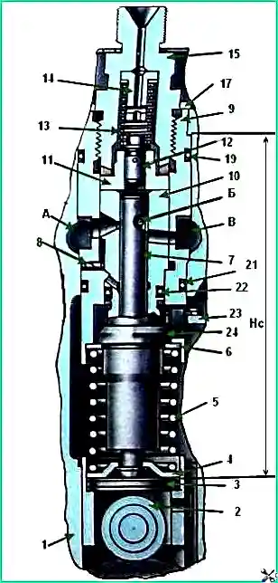
Section of the high pressure fuel pump: 1 - pump housing; 2 - pusher; 3 - pusher heel; 4 - pusher spring plate; 5 - pusher spring; 6 - washer; 7 - plunger; 8 - pin; 9 - pump section housing; 10 - plunger bushing; 11 - discharge valve body; 12 - discharge valve; 13 - discharge valve spring; 14 - spring stop; 15 - fitting; 16 - adjusting washers; 17 - lock washer of the fitting; 18 - flange; 19,21 and 22 - sealing rings; 20 - discharge valve gasket; 23 - left rail; 24 - rotary sleeve; A - fuel injection cavity; B - helical groove of the plunger; B - fuel drain cavity; Hc - size measured at the moment the end of the plunger closes the hole into the cavity
Check the tightness of discharge valves 12 (Fig. 3).
To do this, supply filtered fuel under a pressure of 1.7-2.0 kgf/cm 2 to the pump through a pipeline with a tap and a pressure gauge.
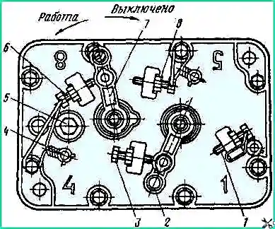
Turn off the fuel supply, for which move lever 7 (Fig. 4) to the rearmost position - all the way to bolt 8 (4 - seal).
Fuel leakage from fittings 15 (see Fig. 3) after 2 minutes after being supplied to the pump is not allowed.
In case of leakage, replace the discharge valve assembly with housing 11.
Check and, if necessary, adjust the opening pressure of the discharge valves with the fuel supply turned off.
To do this, through a pipeline with a tap and pressure gauge, supply filtered diesel fuel through the supply fitting under variable, gradually increasing pressure from 5 kgf/cm 2 to 15 kgf/cm 2
Measure the valve opening pressure using the pressure gauge on the fuel supply line at the pump fitting.
The opening pressure of the discharge valve is taken to be the pressure measured at the moment fuel begins to flow out of fitting 15.
The opening pressure of the discharge valve should be within 9 ÷ 10 kgf/cm 2.
If the valve opening pressure does not correspond to the specified one, adjust it with the thickness of the pack of adjusting washers 16.
As the thickness of the washer pack increases, the opening pressure of the discharge valve increases, and as the thickness of the washer pack decreases, it decreases.
After adjusting the pressure, tighten the fitting (tightening torque 10-12 kgf/m).
When checking and adjusting the start of fuel supply in sections install a torque scope (Fig. 5) on the fitting of the eighth section of the high-pressure fuel pump (Fig. 5), connect the remaining fittings to the injectors.
Through the inlet fitting of the high pressure fuel pump, through a pipeline with a tap and pressure gauge, supply filtered diesel fuel at a pressure of 15-16 kgf/cm 2.
Turn on full fuel supply, for which move lever 2 (see Fig. 4) to the rearmost position - all the way to bolt 1.
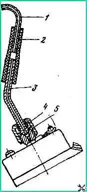
Open the tap, and fuel will flow into the cavity “A” (see Fig. 3) at a pressure of 15-16 kgf/cm 2.
Slowly rotating clockwise (as viewed from the drive side) the pump camshaft by the injection advance clutch, ensure that fuel pressure opens injection valve 12 and fuel begins to flow out of the capillary tube of the momentoscope installed on the fitting of the eighth section of the pump.
Further rotation of the cam shaft by the clutch stops the leakage of fuel from the momentoscope.
When the fuel flow stops from the momentoscope during inspection, the helical groove “B” of the plunger closes the access of fuel from the cavity “A” to the discharge valve and the momentoscope.
The moment the fuel stops flowing from the momentoscope during testing corresponds to the beginning of the displacement (supply) of fuel from the space between the plunger and the discharge valve by the plunger.
Therefore it follows with particular accuracy, catch the moment the fuel flow stops from the momentoscope and use the stand dial to fix the angle at this moment.
This angle of rotation of the pump camshaft will be the beginning of fuel supply by the eighth section of the high pressure fuel pump.
Check and, if necessary, adjust by selecting the pusher heel the start of fuel supply by the eighth pump section.
For a correctly adjusted fuel pump, the start of fuel supply by the eighth section should be 42°30′ ± 30′ before the axis of symmetry of the cam profile.
At the moment the eighth section begins to supply fuel, the marks on the pump body and the injection advance clutch must coincide.
Move the momentoscope in the order of pump operation to the fittings of the remaining sections.
Continuing to rotate the cam shaft by the fuel injection advance clutch in the manner indicated above, determine the moments when the fuel leak from the momentoscope is converted to the remaining sections of the pump, while recording the dial readings on the stand.
These readings will be the moments when each section of the fuel pump starts supplying fuel based on the angle of rotation of the camshaft.
If the angle of rotation of the pump camshaft at which the eighth section began supplying fuel is conventionally taken as the starting point - 0˚, then the remaining sections in the order of pump operation should begin supplying fuel in the following order (in degrees of the angle of rotation of the camshaft): section 8 - 0°; section 4 - 45°; section 5 - 90°; section 7 - 135°; section 3 - 180°; section 6 - 225°; section 2 - 270°; section 1 - 315°
The inaccuracy of the start of fuel supply by any pump section relative to the eighth section is allowed no more than ± 0˚20′.
Adjust the start of fuel supply by installing a pusher heel of the required thickness into the pusher under the plunger.
When installing a heel of greater thickness, fuel begins to flow earlier, when installing a heel of thinner thickness - later.
A change in the thickness of the heel by 0.05 mm corresponds to a change in the angle of rotation of the cam shaft by 0°12′.
The manufacturer provides for the production of the pusher heel in nineteen size groups (Table 2).
Table 2. Designation of size group - pusher thickness: -9 - 3.60-0.05 mm; -8 - 3.65-0.05 mm; -7 - 3.70-0.05 mm; -6 - 3.75-0.05 mm; -5 - 3.80-0.05 mm; -4 - 3.85-0.05 mm; -3 - 3.90-0.05 mm; -2 - 3.95-0.05 mm; -1 - 4.00-0.05 mm; 0 - 4.05-0.05 mm; 1 - 4.10-0.05 mm; 2 - 4.15-0.05 mm; 3 - 4.20-0.05 mm; 4 - 4.25-0.05 mm; 5 - 4.30-0.05 mm; 6 - 4.35-0.05 mm; 7 - 4.40-0.05 mm; 8 - 4.45-0.05 mm; 9 - 4.50-0.05 mm
The number of the size group is marked on the non-working part of the end of the pusher heel.
Checking and adjusting the pump according to the amount of fuel supplied by sections
Check and adjust the pump for the size and uniformity of fuel supply by sections in the following sequence
Instead of the plug, install bypass valve 11 (see Fig. 1) and check the fuel pressure at the inlet to the fuel pump at a camshaft speed of 1300 rpm. Fuel pressure should be 0.6-0.8 kgf/cm 2.
If the pressure differs from the specified one, unscrew the valve plug and adjust with washers.
Diesel fuel must be filtered before being supplied to the pump and have a temperature of 25-30 °C.
Turn on full fuel supply, for which move lever 2 (see Fig. 4) to the rearmost position until it stops against bolt 1.
At a camshaft rotation speed of 1300 ± 10 rpm, check and, if necessary, adjust the average cyclic fuel supply of each pump section, which should be 75.0-77.5 mm/cycle.
The duration of each experiment when determining the volumetric fuel supply should ensure that the volume of measured fuel in the burettes of the stand is at least 20 cm 3.
The unevenness of the cyclic fuel supply across the pump sections should not exceed 5%.
The magnitude of the cyclic flow of each pump section is adjusted by rotating the housing of section 17 (see Fig. 2) relative to the pump housing 1.
When the section body is turned to the right, the cyclic feed decreases, when turned to the left it increases.
Before adjustment, unscrew the nut of the high-pressure pipeline by one or two turns, loosen the tightening of nuts 19 and 22 by ½ turn.
After adjusting, tighten nuts 19 and 22 (tightening torque 2.5-3.0 kgf/m).
Check and, if necessary, adjust with bolt 1 (see Fig. 4) the rotation speed of the pump camshaft at the moment the racks begin to move towards turning off the fuel supply.
Before checking, remove plug 13 of the rack (see Fig. 1). When checking, lever 2 (Fig. 4) should be pressed against bolt 1.
The racks should begin to move at a camshaft speed of 1335-1355 rpm.
Check the camshaft rotation speed corresponding to the complete shutdown of the fuel supply speed regulator through the injectors when lever 2 rests against bolt 1.
Fuel supply at a camshaft speed of 1480-1555 rpm is not allowed.
Check and if necessary It is possible to adjust the camshaft rotation speed corresponding to the start of turning off the fuel supply through the injectors when lever 2 rests on bolt 3.
Complete shutdown of the supply should occur at a pump camshaft speed of 300-350 rpm. Adjust with bolt 3.
If the fuel supply is turned off at a higher camshaft speed, unscrew bolt 3 and tighten it at a lower speed.
Check and, if necessary, adjust the position of bolt 8, which limits the travel of lever 7 in the direction of turning off the feed.
When lever 7 rests on bolt 8, the supply of fuel from the injectors of all sections of the pump at any speed mode of the pump must completely stop.
At the same time, check the power reserve of the racks in the direction of turning off the feed, which should be 0.7-1.0 mm.
Check and, if necessary, adjust the amount of starting fuel supply with bolt 6 at a camshaft speed of 100 ± 10 rpm and lever 2 stops in bolt 1.
The average starting fuel supply should be 195-210 mm 3/cycle. Adjust the amount of starting fuel supply with bolt 6; To increase the feed, unscrew the bolt, to reduce it, tighten it.
After checking and adjusting work, seal the fuel pump in the designated places to prevent the possibility of arbitrary adjustment changes.
In some cases, when operating a vehicle, as well as when performing check adjustment work, it becomes necessary to partially or completely disassemble the high-pressure fuel pump to replace the pusher foot, discharge valve, plunger pair, etc.
Complete disassembly of the high pressure fuel pump:
install and secure the pump on a special stand or in a vice;
- - remove the seals, unscrew the four screws and remove the protective casing 24 (see Fig. 2);
- - remove the seal, unscrew the eight bolts and remove the cover 7 (see Fig. 1) assembled;
- - disassemble the centrifugal speed controller (Fig. 6), for which remove the axis 44 and, without disconnecting, remove the levers 42, 43 and 35, the thrust heel 47 with washers, the spring 37;
- - disconnect the removed parts. To disconnect levers 42 and 43, remove the bushing. In case of emergency, remove spring 39 and lever 36. Remove weight clutch 12 assembled with bearing 11;
- - if the bearing is replaced, remove the retaining ring and press bearing 11 off the coupling. Unscrew plugs 13 (see Fig. 1);
- - unscrew the two nuts and remove the fuel priming pump 29 (see Fig. 2) with pusher spring 31 and manual fuel priming pump 25. If necessary, unscrew the bolt and remove the manual fuel priming pump;
- - unscrew the seven screws and, protecting the gasket from damage, remove the rear cover 1 (see Fig. 6) assembled with bearing 4 and low-pressure pump pusher. Remove gasket 7;
- - open the clamps 34 on the slats, unscrew the two locking screws of the bushings and remove the bushings 9 (see Fig. 1), remove the right 33 (see Fig. 6) and left 38 slats. Undo the cotter pin, remove the washer and rack lever 41;
- - remove the retaining ring 8 and the weight holder 9 assembled with the bearing 23 and weights 13. If necessary, press out the axles 10, remove the weights 13 and compress the bearing 23;
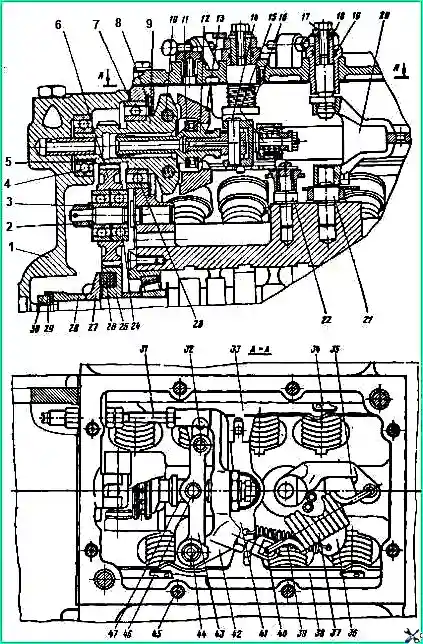
Rotation speed regulator: 1 - rear cover of the regulator: 2, 30 - nut; 3 - washer; 4 - bearing; 5 - adjusting gasket; 6 - intermediate gear; 7 - gasket for the rear cover of the regulator; 8 - retaining ring; 9 - weight holder; 10 - load axis; 11 - thrust bearing; 12 - coupling; 13 - cargo; 14.46 - finger; 15 - corrector; 16 - return spring of the stop lever; 17 - bolt; 18 - bushing: 19 - ring; 20 - regulator spring lever; 21 - spring lever axis: 22 - rack lever axis; 23, 24 - bearings; 25 - drive gear; 26 - drive gear block; 27 - drive gear flange; 28 - fuel pump eccentric; 29 - bending lock washer; 31 - adjusting bolt; 32 - pin; 33 - right rail; 34 - latch; 35 - regulator spring lever; 36 - starting spring lever; 37 - regulator spring; 38 - left rail; 39 - starting spring (rack lever spring); 40 - adjusting bolt of the regulator spring; 41 - rack lever; 42 - regulator lever; 43 - load clutch lever; 44 - axis of the regulator levers; 45 - cover fastening bolt; 47 - persistent heel
- - remove the assembled sections of the fuel pump. To do this, mark the position of the sections relative to the socket in the pump casing - make a core on the casing pump mark and against the marks on flange 23 (see Fig. 2) of the section housing.
This will help during assembly to place the sections in the position in which they were before disassembly.
Unscrew nuts 19 and 22. In this case, it is necessary to rotate the cam shaft so that the pusher and plunger of the section are in the lower position when the nuts are unscrewed.
Otherwise, under the force of the spring 8 of the pusher, the threads of the studs and nuts 19 and 22 may be damaged;
- - remove the lock washers of the fittings, remove the sections and pushers assemblies from the pump body and arrange them in the cells of the portable rack. Screw nuts 19 and 22 by hand onto the studs of the pump housing;
- - unscrew nut 15 (see Fig. 1), remove washer 16 and use puller I-801.16.000 to press coupling 14 from the cam shaft, remove key 17;
- - disassemble the speed regulator drive, to do this, unscrew and unscrew nut 3, remove the washer and remove gear 1 assembled with bearings 2 using a puller.
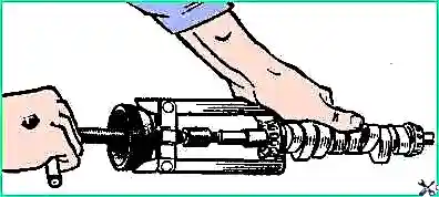
Unlock and unscrew nut 36, install puller I-801.26.000 (Fig. 7) and remove eccentric 34 (see Fig. 1), flange 32, gear 30 with nuts 31;
- - unscrew the screws securing the front 18 and rear 28 camshaft bearing caps, use two screwdrivers to remove the caps from the pump housing and remove the cam shaft 25 assembled with bearings 23 and 27.
On the flanges of covers 18 and 28, for dismantling them with screwdrivers, two diametrically located grooves are made;
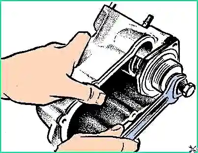
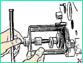
- - install the puller I-801 .29.000 (Fig. 8) and remove the bearings from the cam shaft;
- - install puller I-801.24.000 (Fig. 9) and remove bearing 5 from cover 4 (see Fig. 1);
- - unscrew the locking screw 33 (see Fig. 2), remove the pusher assembly 32;
- - if necessary, disassemble the fuel pump section;
- - unscrew fitting 15 (see Fig. 3), remove spring stop 14 and spring 13 together with the fitting.
Install device I-801.21.000 (Fig. 10) and, pressing the handle of the device, remove housing 11 (see Fig. 3), gasket 20 and discharge valve 12;
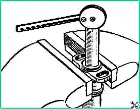
- - compress spring 5, remove plate 4, spring 5 and washer 6. Remove the plunger pair assembly from the housing 9 of the pump section (plunger 7, plunger sleeve 10). Remove rotary sleeve 24 from housing 9.
When disassembling a section, do not touch the working surfaces of the plunger pair with unprotected hands.
Assemble the fuel equipment units in the reverse order of disassembly. The following must be kept in mind.
Depersonalization of the assembled sections of the fuel pump and plunger pushers along the sockets of the fuel pump housing is not allowed - they are matched to each other in terms of dimensional parameters.
Therefore, sections of the fuel pump and plunger pushers should be assembled, if possible, from previously existing suitable worn-in parts and installed in the same slots of the fuel pump housing in which they stood before disassembly.
Parts to be assembled must be clean, rubbing surfaces lubricated with engine oil. Corrosion, dirt, nicks on the working surfaces of parts are not allowed.
Do not wipe parts with cleaning material or handle them with unprotected hands.
New plunger pairs or discharge valves must be washed in filtered diesel fuel.
Before pressing the axles and mounting pins into the pump housing, it must be heated in an oil bath to 80 ÷ 100 ° C, and the pressed parts must be lubricated with engine oil.
Instal rubber sealing rings into the grooves using mandrels without damage or twisting.
Lubricate the lead-in chamfers and surfaces of parts mating with sealing rings and seals with lubricant CIATIM-20I or CIATIM-203 before assembly.
When installing bearings, after pressing the inner ring onto the shaft, check the condition of the inner ring.
Install the front cover 18 (see Fig. 1) carefully, protecting the cuff 20 from damage.
Tighten the cover fastening screws 18 and 28 securely and lock, caulking the body metal into the head slot screw.
When the cover fastening screws 18 and 28 are tightened, the cam shaft should rotate freely in the bearings by hand.
The longitudinal (axial) play of the shaft when applying an axial force of 5-6 kgf should be in the range of 0.01-0.07 mm. Adjust with shims 19.
When assembling plunger pushers, press the pin flush with the supporting surface under the pusher heel.
The pusher roller should rotate freely on the bushing, and the bushing should rotate freely on the roller axis. Jamming in the mating of the specified parts is not allowed.
The pusher and block assembly, lubricated with engine oil, must move freely in the fuel pump socket under the influence of gravity.
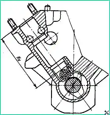
If you replace the cam shaft, fuel pump housing or plunger pushers, measure the sections of the fuel pump housing - size "Hc" (Fig. 11).
When taking measurements, install the cam shaft so that the plunger pusher of the section being measured is in the lowest position.
If you replace the plunger pair of the newly assembled section, measure the dimension “Hk” (see Fig. 3). Dimension “N” is measured at the moment the end of the plunger 7 closes the hole from the discharge cavity “A”.
According to the results of measurements and table. 3 determine the group number and clearly mark this number against the section socket on the fuel pump housing, flange 18 of the section housing. Coin the previous group numbers.
Table 3. "Hk" - fuel pump housings - "Hc" - fuel pump sections - group number:
- 117.80-117.85 mm - 110.70-110.75 mm - 0;
- 117.85-117.90 mm - 110.75 -110.80 mm - 1;
- 117.90-117, 95 mm - 110.80-110.85 mm - 2;
- 117.95-118.00 mm - 110.85-110.90 mm - 3;
- 118.00-118.05 mm - 110.90-110.95 mm - 4;
- 118.05-118.10 mm - 110.95-111.00 mm - 5;
- 118.10-118.15 mm - 111.00-111.05 mm - 6;
- 118.15-118.20 mm - 111.05-111.10 mm - 7;
- 118, 20-118.25 mm - 111.10-111.15 mm - 8;
- 118.25-118.30 mm - 111.15-111.20 mm - 9
The difference between the group numbers of the section socket in the pump body and section 1 assembly will determine the group number and the size of the pusher heel 3.
When assembling a fuel pump section with a new plunger pair, additionally check the ease of movement of the plunger along the entire stroke length and angle of rotation; Jamming of the plunger in the bushing is not allowed.
Check that the plunger shank 7 is buried in plate 4.
The lower end of the plunger 7 should not reach the plane of the plate 4 by 0.1-0.3 mm.
When assembling, lubricate fitting 15 with diesel fuel and tighten (tightening torque 10-12 kgf/m).
After assembly, check the ease of rotation of the rotary sleeve 24 with the compressed spring of the pusher 5. The sleeve is not allowed to jam.
Install the assembled sections into the fuel pump housing so that the section mounting studs are in the middle of the holes in the section housing flange.
In this case, the slots on the housing of the section for installing the rack and the mark on the plunger should face the cavity in the pump housing for the regulator.
Tighten nuts 19 and 22 (see Fig. 2) securing the flange 23 of the fuel pump section (tightening torque 2.5-4.5 kgf/m).
After tightening nuts 19 and 22, check the smooth movement of the rack when turning the cam shaft.
After adjusting the start of fuel supply by the pump sections, check the fuel pump for leaks in the low pressure fuel line using the following method.
Drain the fuel from the low pressure line, plug the bypass valve hole with a plug.
Immerse the fuel pump in a bath of diesel fuel so that the threads of fittings 21 are above the level of the fuel surface. Supply air through the fuel supply fitting into the low pressure fuel line.
The fuel system of the pump is sealed if, with a gradual increase in pressure at a speed of 1.5 kgf/cm 2/min from 0.5 kgf/cm 2 to 5 kgf/ cm 2 no air bubbles are observed from the pump.
When assembling the regulator check that gear 25 (see Fig. 6) on the cam shaft rotates without jamming.
After installing the damper parts (gear 25, block 26, spacer, key, flange 27 and eccentric 28), tighten nut 30 (tightening torque 4-6 kgf/m) and secure with washer 29.
Circumferential play in the gear damper parts is not allowed.
The regulator loads should differ in static moment by 2x10 kgf/m, no more. The weights installed on the holder must swing freely on their axes under the influence of their own weight.
Before pressing the bushing onto coupling 12, heat the bushing in an oil bath to 80-100 °C, and lubricate the coupling with engine oil.
Must be free, without jamming or sticking, move and turn:
- - coupling 12 in holder 9;
- - thrust heel in clutch 12 and on pin 14 of the load clutch lever.
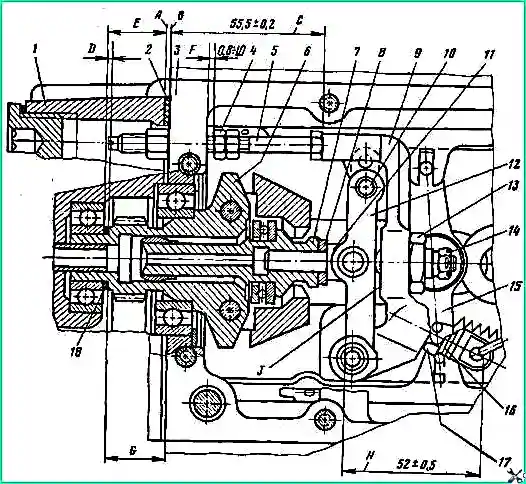
Speed regulator; 1 - rear cover of the regulator; 2 - gasket for the rear cover of the regulator; 3 - pump housing; 4- limit nut; 5 - lever adjusting bolt; 6 - regulator weight holder; 7 - regulator weight coupling; 8 - gauge-device; 9 - regulator lever 10 - pin; 11 - thrust heel of the load clutch: 12 - lever of the load clutch; 13 - corrector body nut: 14 - corrector nut; 15 - rack lever; 16 - spring adjusting bolt; 17 - lock nut; 18 - adjusting shims
When assembling levers 9 and 12 (Fig. 11), ensure that the adjusting bolt 16 of the regulator spring is screwed into lever 9 to size H = 52 ± 0.5 mm and locked with nut 17.
Adjust the preload of the corrector spring with nut 14. It should be equal to 15-16 kgf.
After adjustment, secure nut 14 with a cotter pin. Wrap the corrector body into lever 9 so that the corrector head protrudes beyond the “J” plane by 0.05-0.15 mm.
After installation, secure the corrector body with nut 13.
When assembling the top cover, ensure the following
Before pressing in the bushings, heat the cover to 80-100° C, and lubricate the bushings with engine oil.
Return spring 16 (see Fig. 6) should return lever 7 (see Fig. 4) to its original position (until it stops against bolt 6).
Wrap the adjusting bolts for limiting the stroke of levers 2 and 7 into bosses and secure with nuts.
Moreover, bolts 3 and 6 should protrude from the bosses by 2-4 and 8-10 mm, respectively, and bolts 1 and 8 should be screwed flush with the ends of the bosses.
When assembling cover 1 (see Fig. 6), before pressing in bearing 4, heat the cover to 80-100° C.
After pressing, cool the cover to 20 ± 3° C and measure the dimension “E” (see Fig. 12) from the mating plane “A” of the cover to the end of the holder bearing.
When installing parts into the high pressure fuel pump housing, ensure the following.
The adjuster levers should move freely without jamming, and the bearing retaining rings should be in their grooves.
Install the regulator springs 37 (see Fig. 6) and starting feed 39 so that the free end of the spring hook is directed downwards towards the cam shaft.
The protrusion of the end of the head of bolt 5 (see Fig. 12) from the mating plane “B” of the pump housing should be equal to dimension C = (55.5 ± 0.2 mm).
The gap between the fuel pump housing 3 and the limit nut 4 should be equal to the size "F" = (0.8-1.0 mm).
Adjusting bolt 5 and limit nut 4 must be locked.
Before installing lever 35 (see Fig. 4), check the force of movement of lever 43 connected to the slats by pin 32 in the direction of the axis of the weight coupling.
With a stationary cam shaft, this force should be no more than 0.15 kgf in the middle position of the racks, and 0.6 kgf in the extreme positions.
When installing the regulator parts into the high-pressure fuel pump housing, determine the thickness "E"of the shim pack 18 (see Fig. 12).
The thickness of the package of adjusting shims 18 affects the power reserve of the racks in the direction of turning off the fuel supply when the regulator loads are fully extended, the cam shaft rotation speed is 500-550 rpm and the lever 2 (see Fig. 4) rests on bolt 3.
As the thickness of the gasket package decreases, the power reserve of the racks increases, and as the thickness increases, it decreases.
To perform this work, move weight coupling 7 (see Fig. 12), holder 6 assembled with weights in the axial direction towards rear cover 1.
In the resulting gap between coupling 7 and fifth 11, install a gauge-device with a thickness of 3.75-0.026 mm.
After installing the gauge-device, rest lever 9 against the head of bolt 5, lever 12 against lever 9; At the same time, move the holder 6 with coupling 7 to the heel 11 so that they are clamped:
- - gauge-device between coupling 7 and fifth 11;
- - weight rollers between the platform of the holder 6 and the coupling 7. With this position of the holder 6, measure dimension G - the protrusion of the end of the holder beyond the mating plane “B” of the pump housing.
Using the formula, determine the thickness D of the shim package 18:
B = E +0.6 – G
In this formula, the dimensions of E and G were determined by measurements, 0.6 is the thickness of paronite gasket 2.
You can also determine the thickness D of a package of adjusting shims if you have a gauge-device with a thickness of 3.75-0.025 mm and a set of feeler gauges.
At the same time, there are 3 installations on the pump housing Thread and secure the back cover 1 with gasket 2 with screws. Move the holder 6 with coupling 7 towards the cover 1 until the end of the holder stops against the cover bearing.
Press lever 9 to the head of bolt 5, lever 12 to lever 9 and install a gauge - device and a package of feeler gauges into the gap formed between the heel 11 and coupling 7.
The thickness of the stylus package must be such that the weight rollers are clamped between the weight holder platform and the weight coupling.
The thickness of the probes will determine the thickness "E" of the gasket package 18. After completing the work, remove cover 1 and install the gasket package 18 with thickness "E", check the locking of nuts 3 and 36 (see Fig. 1).
Install the cover on the pump housing and secure with screws.
Install the three upper screws securing the back cover with sealant paste. The difference between the determined thickness "D"of the gasket package and the actually installed one should not exceed 0.1 mm.
After assembly, make sure that the travel reserve of the racks in the direction of turning off the feed is at least 0.5 mm with the regulator weights fully extended.
In the assembled regulator, all parts should move without jamming.
The control and shutdown levers of the regulator must return clearly to their original position under the action of the springs.
When assembling the low pressure fuel pump and manual fuel priming pump, please note the following.
The low pressure fuel pump rod and bushing are a precision pair that must not be disassembled.
If it is necessary to replace one of the parts, replace them as a whole.
Install a new bushing with a rod into the body using epoxy glue. After drying the glue, check the tightness of the housing with air under pressure 4÷6 kgf/cm 2.
The body and piston of the low-pressure fuel pump are divided into two size groups according to the diameter of the cylinder and piston, respectively; the cylinder and piston of the hand pump are divided into three size groups.
The group number is marked in a visible place on the parts. In case of replacement, the newly installed part must be of the same size group.
When assembling the low pressure fuel wear parts and the hand pump, lubricate (moisten) with filtered diesel fuel
Tighten the threaded connection of the hand pump cylinder to the cylinder body and the bolt securing the hand pump assembly to the low pressure pump body. The tightening torque should ensure the tightness of the connection.
When assembling the automatic fuel injection advance clutch, do not depersonalize the loads.
Based on the static moment relative to the hole for the load axle, they are divided into six size groups.
The difference in the static moment of loads of one group should be 8x10 kgf/m, no more.
Before assembling the parts of the fuel injection advance clutch, lubricate them with engine oil.
Tighten the threaded connection of housing 1 with driven coupling half 9 (tightening torque 25-28 kgf).
After assembly, the high-pressure fuel pump assembly with the low-pressure pump and the injection advance clutch is run for an hour in bench conditions on diesel fuel with a camshaft rotation speed of 1000 ± 50 rpm.
When running on a stand, the pump should be lubricated with forced circulation of filtered engine oil under a pressure of 1-7 kgf/cm 2.
Before testing, pour 0.16-0.20 liters of engine oil into the pump through the hole closed with plug 5 (see Fig. 4) and into the coupling through the holes closed with screws 13.
The fuel pressure in the low pressure line of the fuel pump should be 0.5-2 kgf/cm 2.
For the first 10 minutes of running-in, lever 2 (see Fig. 4) should be against bolt 3.
Over the next 50 minutes, lever 2 should move between bolts 1 and 3 with a frequency of 10-12 complete movements per minute.
Carry out break-in with a tested set of injectors.
During the running-in of the pump, knocks and extraneous noise are not allowed. The oil temperature at the outlet of the fuel pump should not exceed 80° C.
If a knocking sound, extraneous noise or any other malfunction is noticed during running-in, stop running-in, disassemble the pump, eliminate the fault and reassemble the pump.
Repeat the pump running-in in full if, when troubleshooting, at least one of the following parts (assemblies) was replaced with a new, non-run-in one: fuel pump housing, plunger pair, cam shaft with bearings, plunger pusher, discharge valve, regulator drive gear , weight holder, thrust heel, adjuster levers, adjuster rear cover, rack, housing, or piston, or pusher of the low pressure fuel pump.


