To check or set the fuel injection advance angle correctly, you need to know:
- - engine crankshaft position during the compression stroke in the first cylinder;
- - for the high pressure fuel pump, the position of the cam shaft is at the beginning of the fuel supply by the eighth section.
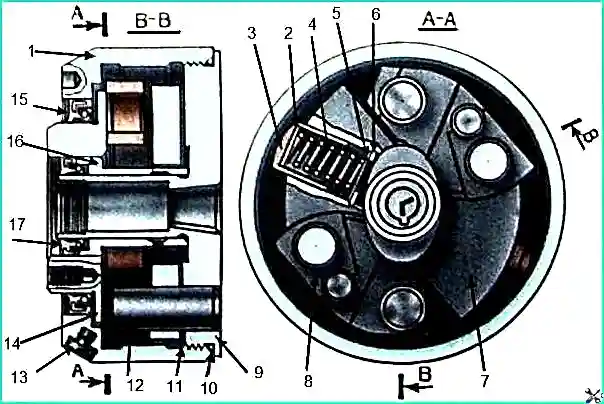
In order to quickly and accurately identify and install the engine crankshaft and the camshaft of the high-pressure fuel pump into the indicated positions, marks are applied to the fuel pump housing, the automatic fuel injection advance clutch and the rear flange of the drive coupling half.
In Fig. 2 these marks are respectively designated “A”, “B” and “C”.
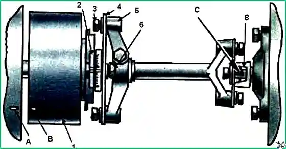
The fuel injection advance angle is set correctly if the marks “A” and “B” on the fuel pump housing and the fuel injection advance coupling are aligned, and the mark “C” on the rear flange of the drive half is in the upper position, to install the rear flange 8 to the position in which the mark “C” takes the upper position along the clamp, it is necessary to unscrew the bolts and remove the cover of the lower hatch of the clutch housing.
Inserting a crowbar into the holes in the flywheel, turn the crankshaft to a position in which the “C” mark moves from bottom to top.
At this moment, turn the flywheel lock pin 90˚ and lower it into the deep groove.
Continue to rotate the crankshaft using a crowbar by the flywheel until the clamp enters the hole in the flywheel.
This will be the upper fixed position of the “C” mark on flange 8; in this case, the compression stroke will end in the first cylinder.
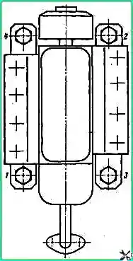
Align the marks “A” and “B” on the pump housing and the fuel injection advance coupling, install the pump and bolt it to the engine block.
Tighten the bolts securing the pump to the block evenly, in several steps, in the sequence shown in Fig. 3.
Without disturbing the mutual alignment of the positions of the marks “A” and “B” on the pump body and the fuel injection advance coupling, connect the upper end of the driven coupling half 2 with the front plate 4 with bolts 6 (see Fig. 2).
Install the lock pin into the shallow groove, turn the crankshaft one turn, install and tighten the second bolt 6.
When a compressor and power steering pump are installed on the engine, flange 8 (especially the mark on the flange) is difficult to see.
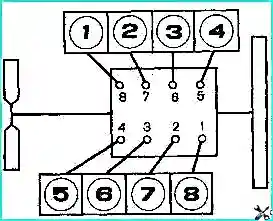
In this case, it is more convenient to determine the upper position of the mark “C” on the rear flange 8 of the drive half of the coupling using the valves.
To do this, remove the head cover of the first cylinder (Fig. 4), and turn the crankshaft using a crowbar by the flywheel until the suction valve begins to close (the front valve from the fan).
Move the retainer pin into the deep groove and continue rotating the crankshaft until the retainer enters the hole in the flywheel.
This will be the fixed position of the crankshaft, at which mark “C” of flange 8 (see Fig. 2) will be in the upper position.
After installing the pump on the engine, connecting the control drive to it, oil supply (outlet) pipes, fuel lines and high pressure pipes, additionally check and clarify the setting of the fuel injection advance angle.
To do this, move lever 2 (see Figure 5) for controlling the regulator to the middle operating position and lower it all the way into bolt 3.
Pump the engine power system with a manual booster pump for 2-3 minutes.
Rotate the crankshaft half a turn counterclockwise, as viewed from the fan side, and move the lock pin into the deep groove.
Slowly rotate the crankshaft as it rotates until the retainer fits into the hole in the flywheel.
If the marks on the pump housing and the injection advance coupling are aligned, then the injection advance angle is set correctly.
If the marks are not aligned, then loosen the upper bolt 6 (see Fig. 2) of the driven coupling half, install the lock pin in the shallow groove, turn the crankshaft one revolution in the direction of rotation and loosen the second bolt 6.
Turn the injection advance clutch against the stroke (counterclockwise, when viewed from the flywheel) until the bolts stop in the groove of the front plate 4.
Lower the flywheel lock into the deep groove and turn the crankshaft in the direction of rotation until the lock aligns with the hole in the flywheel.
Turn the injection advance clutch by the flange of the driven coupling half 2 in the direction of rotation until the marks on the pump body and the advance clutch align.
Tighten the upper bolt 6, move the flywheel lock pin into the shallow groove, turn the crankshaft one turn and tighten the second bolt 6.
Check the accuracy of the marks on the pump body and the injection advance clutch again in the same way.
After installing and checking the fuel injection advance angle, start the engine, warm it up to a coolant temperature of 80˚ C and use bolt 3 (see Figure 5) to adjust the minimum crankshaft speed, which should not exceed 600 rpm.


