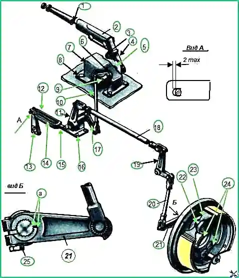
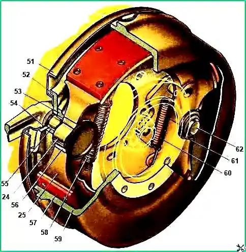
Drum-type parking brake with mechanical drive (Fig. 1)
The parking brake drive is connected by lever and rod to lever 13 of the brake valve, which ensures that when the vehicle is braked with the parking brake, the service brake system of the trailer (semi-trailer) is activated.
The parking brake is mounted on the transfer case.
The brake shield with pads is attached to the bearing cover of the rear axle drive shaft, and the brake drum is on the flange of this shaft.

The parking brake and its drive are partially or completely disassembled mainly when the braking efficiency decreases, which cannot be eliminated by adjusting the drive, as well as when the reliability of fixing the parking brake lever in the braked state decreases.
The reasons for reduced braking efficiency may be oiling, destruction from heat or complete wear of the brake pad linings, as well as loosening of the bolts securing the brake shield to the transfer case.
The reason for the violation of the lever fixation is wear of sector 5 or pawl 4 of the lever.

Disassembly and removal of parking brake parts
Unscrew the nuts and remove the propeller shaft of the middle axle drive.
Unscrew the nut and remove the bolt securing the ejection pipe to the third cross member of the frame.
Unscrew the two screws securing the drum to the flange, lift the ejection pipe up and remove the drum.
Remove tension springs 24 and pads 23.
Unpin and remove the pin, disconnect rod 20 from lever 21.
Unscrew and unscrew the flange mounting nut, press the flange from the rear axle drive shaft of the transfer case.
Unscrew the bolts and remove the oil trap, gasket and brake shield assembly.
Unscrew bolt 25 and remove adjusting lever 21.
Remove the locking ring and remove the expansion fist 22.
If necessary, press the expansion knuckle bushing out of the shield bracket. (It is not recommended to press out the axis of the pads from the lower bracket of the shield).
Disassembly and removal of parking brake drive parts
Unpin and remove the pin connecting rod 10 to lever 6.
Unscrew the four bolts 8 in the cabin and remove the bracket assembly.
Unsplit and remove the pins connecting rod 18 to levers 11 and 19, rod 15 to levers 13 and 17, rod 10 to lever 17.
Unsplit the lever axis 19, remove the washer and lever.
Unscrew the four bolts and remove bracket 16 assembled with levers.
Disassemble bracket 7, to do this, unscrew the bolt securing lever 3 on shaft 9 and remove the lever assembly with pawl 4, lever 2 and pawl rod 1.
Remove lever key 3 from shaft 9.
Unscrew the flange mounting bolts and the lever mounting bolt 6 on shaft 9, remove the flange.
Press shaft 9, complete with key, out of lever 6 and out of the bracket through the hole for the flange.
Remove the lever key 6 from shaft 9. If necessary, unscrew the two bolts and remove sector 5.
Press the bushings out of bracket 7 and flange.
Unscrew the bolt and remove lever 11 from the shaft and its key.
Remove the shaft assembly from bracket 16 with lever 17, which is pressed onto the splined end of the shaft.
It is not recommended to disconnect the splined end of the shaft from lever 17. If necessary, press 16 bushings out of the bracket.

Dimensions for checking the main parts are given in Table 1.
Table 1.Dimensions for checking handbrake parts
Handbrake shoe axis. Outer diameter at the place of pad support:
- - nominal size - 28.15+0.100 mm;
- - permissible size - 28.10 mm
Extension fist bushing. Inner diameter:
- - nominal size - 25+0.150 mm;
- - permissible size - 26.00 mm
Expanding fist. Neck diameter for bushing:
- - nominal size - 25-0.025 mm;
- - permissible size - 24.85 mm
Parking brake lever shaft. Outer diameter:
- - nominal size - 20-0.080 mm;
- - permissible size - 19.80 mm
Clutch pedal shaft bushing. Inner diameter:
- - nominal size - 20+0.150 mm;
- - permissible size - 21.00 mm
Sleeve. Inner diameter:
- - nominal size - 20.45+0.100 mm;
- - permissible size - 21.00 mm
Intermediate shaft. Outer diameter for bushing:
- - nominal size - 20-0.025 mm;
- - permissible size - 19.80 mm
Brake drum. Inner diameter:
- - nominal size - 300+0.34 mm;
- - permissible size - 303.34 mm
Worn linings, if less than 0.5 mm remain from their surface to the rivet heads, should be replaced.
If there is significant and uneven (with annular grooves) wear on the working surface of the brake drum, it, as well as the pad assembly with linings, must be ground to repair dimensions (Table 2).
Table 2.
Inner diameter of brake drum:
- Nominal size - 300+0.34 mm;
- First repair - 301+0.34 mm;
- Second repair - 302+0.34 mm;
- Third repair - 303+0.34 mm
Outer diameter of pads by linings:
- Nominal size - 300-0.25 mm;
- First repair - 301-0.25 mm;
- Second repair - 302-0.25 mm;
- Third repair - 303-0.025 mm
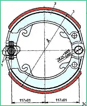
When turning on a machine, the pads should be based as shown in Fig. 3. At the same time, install 1 mm thick plates between the expansion fist and the pads.
Oily linings of the brake pads must be washed with unleaded gasoline and then dried.
Linings that have a loose composition on the working surface and peeling due to overheating must be replaced.
Cracks and other damage to the pads are not allowed. If the fastening of the crackers to the toes of the pads becomes loose, the screws should be tightened.
Assemble the parking brake and its drive in the reverse order of disassembly. In this case, the following requirements must be met:
- - when installing the brake shield on the transfer case, the oil trap gasket must be lubricated with sealing lubricant (the tightening torque of the shield mounting bolts should be 8.0-10 kgf/m);
- - lubricate the expansion knuckle and its bushing, the axle of the pads and brake pads at the point of support on the axle, as well as the axles and bushings in the parking brake drive with graphite grease;
- - when installing tension springs 24 (see Fig. 1), install a spring with a diameter of 28 mm at the expansion fist, and a spring with a diameter of 20 mm at the axis of the pad support;
- - marks “a” on the splined ends of the expanding fist 22 and the adjusting lever 21 during assembly;
- - install lever 6 with the machined side to the right inner wall of bracket 7.
After assembly, the parking brake must be adjusted. In this case, lever 2 should be in the lowest position on the stop.
In the connection of bracket 12 with lever 13 of the brake valve, be sure to set the gap to 2 mm, changing the length of rod 15.
By changing the length of the rod 18 and moving the lever 21 on the splines of the expansion knuckle 22, adjust the gap between the brake pads and the drum, which should be within 0.3-0.6 mm.
With a correctly adjusted parking brake, the stroke of lever 3 during full braking should be four to six sector teeth, and the drive lever should be locked.
After running in the brake pads, you should check the effectiveness of the parking brake.


