Service brakes are disassembled during maintenance and troubleshooting (oiling, wear and tear of brake pad linings, wear or damage to the sealing collars of wheel cylinders, breakage of the tension spring, etc.)
Removing and disassembling service brake parts
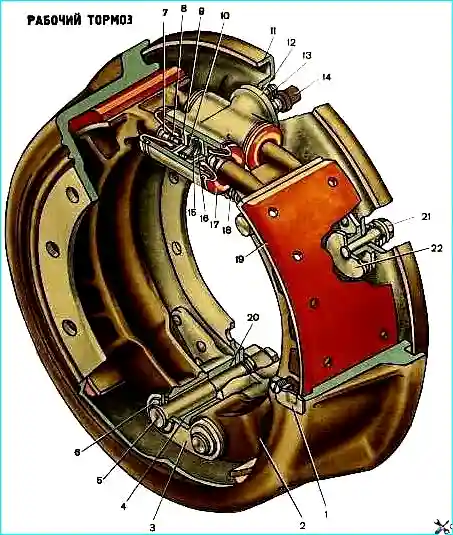
Remove the wheel and hub assembly with the brake drum, clean the brake mechanism from dirt and wash it.
Using the mounting blade as a lever, disconnect tension spring 2.
Remove locking brackets 9, linings 8 and brake pads 6 from the axles 11 pads.
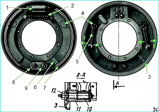
Disconnect brake fluid supply line 1 from the wheel cylinder, unscrew the bolts securing it to the shield and remove the cylinder assembly.
If necessary, unscrew the bolts and remove the brake shield.
If the pad linings or pad assemblies cannot be replaced, then unscrewing the nuts 12 and turning the axles 11 in the shield bracket is not recommended, which will allow the pads to take their previous position relative to the brake drum during assembly, and, therefore, will make it easier to adjust the gaps between the pad linings and brake drum.
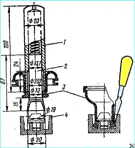
When disassembling the wheel cylinder, remove the springs of the caps 1 (Fig. 3), caps 2, assembled with pistons 4.

Remove cuffs 5, cuff holders 6 and spring 9.
After disassembling, wash the wheel cylinder parts in alcohol or brake fluid, and the mechanical brake parts in unleaded gasoline.
Washed parts should be carefully inspected and, if necessary, measured.
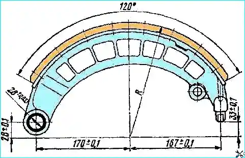
If the depth of the rivet heads for fastening the linings is 0.5 mm or less, then the linings should be replaced with new ones.
Pistons, cuffs and cylinders if there are marks or significant wear on the working surfaces must also be replaced with new ones.
You should especially carefully inspect the protective caps of the cylinders, since the durability and reliability of the wheel cylinder as a whole depend on their condition.
In case of through breaks and cracks, the cap must be replaced using the device (Fig. 4).
Dimensions for checking the main parts of the service brake are given in Table 1.
Table 1. Dimensions for checking the main parts of the service brake
Brake pad support bracket:
- - nominal diameter of the holes for the axles of the pads - 22 +0.045 mm;
- - permissible diameter of holes for the axles of the pads - 22.10 mm
Brake pad axis:
- - nominal outer diameter of the journal for the pad bushing 28 - 0.025 mm;
- - permissible outer diameter of the journal for the pad bushing is 27.85 mm
Wheel cylinder:
- - nominal diameter of the piston hole - 35 +0.027 mm;
- - nominal diameter of the piston hole - 35.06 mm;
Wheel cylinder piston:
- - nominal outer diameter - 35.0075 mm;
- - permissible outer diameter - 34.85 mm
Brake shoe assembly:
- - nominal inner diameter of the bushing - 28 +0.033 mm;
- - permissible inner diameter of the sleeve - 28.10 mm
Brake drum:
- - nominal inner diameter of the drum - 420 +0.380 mm;
- - permissible inner diameter of the drum - 424.40 mm
If there is significant wear and the presence of annular grooves on the working surface of the brake drum, grind it, as well as the pads and linings, to one of the repair dimensions indicated in Table 2.
Table 2
Repair dimensions - Inner diameter of the brake drum, mm - Outer diameter of the pads on the linings 2R mm:
- Nominal - 420 +0.38- 420 -0.60
- First - 421 +0.38- 421-0.60
- Second - 422+0.38- 422-0.60;
- Third - 423+0.38- 423-0.60
When grooving, base the brake drum on the inner surfaces of the outer rings of the hub bearings, and the pads as shown in Fig. 5.
Assemble the wheel brakecarry out in the reverse order of disassembly, and a number of the following mandatory requirements must be met:
- lubricate the wheel cylinder mirror, piston and sealing lip with brake fluid. Apply graphite lubricant to the pad bushings.
Before connecting the wheel cylinders to the vehicle’s hydraulic system, replace the brake fluid and clean the fluid reservoir on the pneumatic boosters from sludge.
Before installing the hub with the brake drum, bring the pads inward using adjusting eccentrics 4 (Fig. 2) and install the axes of the pads in a position in which the installation marks on the ends of the axles are directed backward at the axis of the front pad, and forward at the rear axis.
If during disassembly the position of the axes of the pads on the brake shield is not disturbed, and during assembly the pads are installed in their places, then adjust the gaps between the pads and the brake drum only with eccentrics 4, turning them (see Fig. 2) until the wheel will not brake.
Then turn the eccentric in the opposite direction until the wheel rotates freely (the wheel must be rotated towards the adjustable block).
After adjustment, check the gap through the hatch in the brake drum with a feeler gauge 200 mm long at a distance of 30 mm from the edges of the lining.
The gaps should be 0.35 mm at the toe (top of the last) and 0.20 mm at the heel (bottom of the last).
After replacing the brake linings or installing other pad assemblies, as well as if the position of the axes of the pads on the shields is violated, the gaps should be adjusted using eccentrics 4 and axes 11 of the pads.
At this time, turn the eccentric 4 to slow down the rotation of the wheel.
By turning the axis 11 of the block, determine the direction of its rotation in which the wheel will rotate freely.
Continue rotating the pad axis in the same direction until the wheel is completely braked.
The angle of rotation of the block axis from the first braked state of the wheel to the second is divided in half and install the axle in this position.
Repeat this operation several times. Each time the angle of rotation of the pad axis from the first braked state of the wheel to the second will decrease.
After completing the adjustment, make a gap of 0.20 mm at the heel of the pad, for which insert a 0.20 mm feeler gauge between the drum and the heel of the pad and lightly tighten it by turning the axis of the pad.
In this case, the gap at the toe of the pad should be 0.35 mm. If the clearance at the toe of the pad is different, the adjustment should be continued.
After adjusting the brakes of all wheels, install the axle shafts and bleed (fill) the hydraulic system with brake fluid, having first thoroughly cleaned the outer surfaces of the main brake cylinders, brake fluid reservoirs and bypass valves from dirt.
Filling the system with liquid and pumping the brakes is only possible if there is air (7.5 kgf/cm²) in the car’s pneumatic system.
Before filling, thoroughly remove dirt from the master cylinders and reservoirs.
Then, removing sealing tubes 1 from both cylinders (Fig. 6) and unscrewing the filler plugs 2, fill the reservoirs with brake fluid.
Bleed air from the main cylinders through bypass valve 3.
The procedure for bleeding the main cylinders and service brake cylinders:
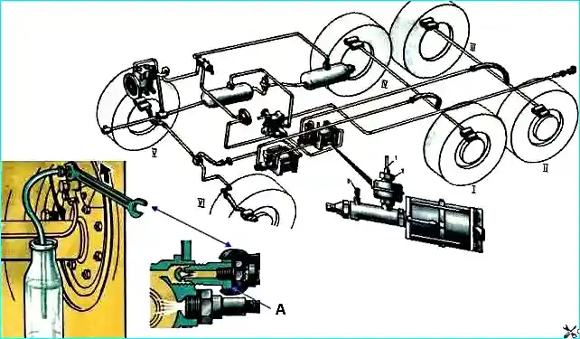
Remove the rubber cap from bypass valve 3 (Fig. 6), put on it the tube included in the tool kit (Fig. 6), lower its open end into brake fluid poured into a glass vessel with a capacity of at least 0.2 l;
Unscrew the bypass valve ½ - ¾ turn, then press the brake pedal several times.
Press quickly and release slowly. Repeat pressing until the release of air bubbles from the tube stops.
During the pumping process, it is necessary to add liquid to the tanks, avoiding a “dry bottom”, since this will allow air to enter the system again.
Pressing the pedal, tightly tighten the cylinder bypass valve, remove the tube and put on the cap.
In the same way, pump the wheel brake cylinders through the bypass valve (Fig. 6) in the following sequence (Fig. 6):
I - middle left, II - rear left, III - rear right, IV - middle right, V - front right, VI - front left.
After bleeding all cylinders, add fluid to the tanks to a level of 15-20 mm below the upper edge of the filler neck, tightly screw the filler plug, and attach the sealing tube.
When replacing brake fluid, disassemble the wheel and master cylinders, wash the working surfaces of the parts.
When assembling the wheel cylinders, lubricate the piston and the inner surface of the cylinders with castor oil.


