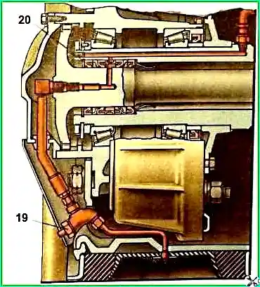
The tire pressure regulation system consists of a pressure control valve, an inter-cylinder reducer, a block of tire valves, a block of air supply seals in the axle housing, wheel valves and pipelines
Air is supplied to the control system from air cylinders 11
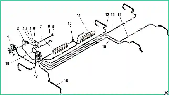
The spool-type tire pressure control valve consists of a body 1 in which two oil seals 5 and a spool 9 are installed
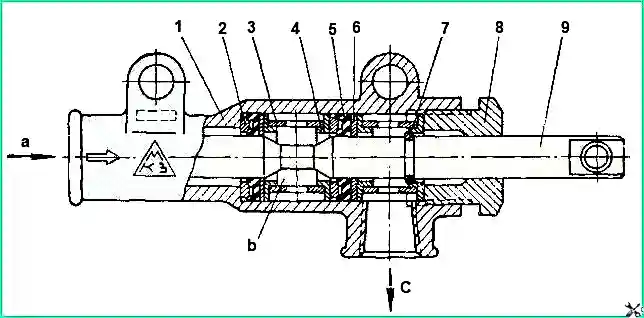
When the spool moves along its axis, the annular groove on it connects the valve cavity either to the atmosphere or to the discharge line
The pressure control valve lever can be installed in three positions:
- - left position – tire inflation;
- - average – neutral;
- - right – releasing air from the tires into the atmosphere
Air is supplied to the tire valve block from the pressure control valve
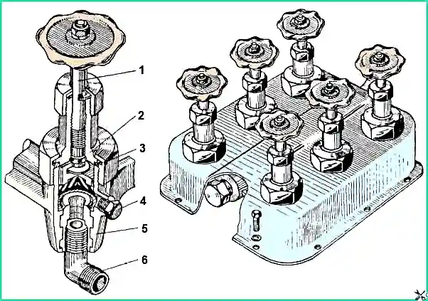
The block has six valves with handwheels according to the number of buses
The purpose of each valve is shown in the figure
When the valves are open and all the tires of the car are connected to each other, the pressure in them is the same
In this case, inflation and deflation of air can be carried out simultaneously for all tires
Tire air pressure is monitored using a pressure gauge included in the tire pressure regulation system
The air supply seal block is installed in the wheel axle and consists of four seals
Two middle oil seals ensure a tight connection between the channels of the fixed axle and the channels of the rotating axle
Two outer seals serve to retain lubricant at the working surfaces of the air supply seals
The inter-cylinder gearbox is installed between the air cylinders on the right side member of the vehicle
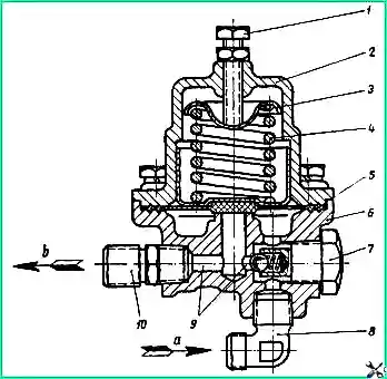
The gearbox in the brake system sets the pressure necessary for the safe movement of the car
When the air pressure in the first (front) cylinder reaches above 5 kg/cm² valve 5 opens, and air enters the second cylinder through elbow 8, channels 9 and fitting 10
When the pressure in the brake system drops below 4.5 kg/cm² valve 5 closes and the power to the system is automatically turned off
If the pressure in the first cylinder is lower than in the second by 0.5 kg/cm², then the gearbox allows you to use the reserve of compressed air from the second cylinder for the brake system
In this case, air flows from it through fitting 10, check valve 7 and elbow 8 to the first cylinder
Use and care of the tire air control system
While driving, the valves of the tire valve block and wheel valves must be fully open, and during long-term stops, in order to avoid air leakage through leaks in the pipelines, they must be closed.
Tire air pressure is determined using a pressure gauge at neutral the position of the pressure control valve lever and the open wheel valves and valves of the tire valve block.
If there is a drop in pressure, then by closing all the valves and opening them one by one, you can determine which tire is leaking air
The pressure regulation system allows you to continue driving the car in the event of a tire damage, without immediately having to replace the wheel
But at the same time, the compressor performance must be sufficient to compensate for leakage from the damaged chamber and provide the necessary pressure in the brakes
Tire pressure and driving speed must be set in accordance with the nature of the road surface (Table 1)
Table 1. Tire pressure depending on road surface
Wattened meadow, marshy area:
- - permissible air pressure - 0.5-0.75 kgf/cm²;
- - maximum vehicle speed - 10 km/h
Fast sand, wet arable land, virgin snow:
- - permissible air pressure - 0.75-1.4 kgf/cm²;
- - maximum vehicle speed - 20 km/h
Soaked dirt roads, loose soil, damp meadow:
- - permissible air pressure - 1.4-1.7 kgf/cm²;
- - maximum vehicle speed - 20 km/h
Roads of all types (only for the pumping period):
- - permissible air pressure - From 1.5 to 3.2 kgf/cm²;
- - maximum vehicle speed - 30 km/h
If it is necessary to reduce tire pressure, set it depending on driving conditions.
Maintenance of the system consists of checking its tightness.
Determine places of large leakage by ear, places of weak leakage with soap emulsion.
Eliminate air leaks through connections by tightening or replacing a separate element of the connection.
If the pressure control valve, wheel valves and pipeline connections are sealed during inspection, then the leak occurs through the air supply cuffs. If there is a large leak, replace the cuffs.
The reliability of the air supply cuff unit primarily depends on the presence and condition of the lubricant on their rubbing surfaces.
When installing the cuffs, lubricate these surfaces and put grease in the cavity between the first and second, as well as between the third and fourth cuffs.
When installing the axle shaft, also thoroughly lubricate the surface of the working journal, and the lubricant should not get into the air supply hole.
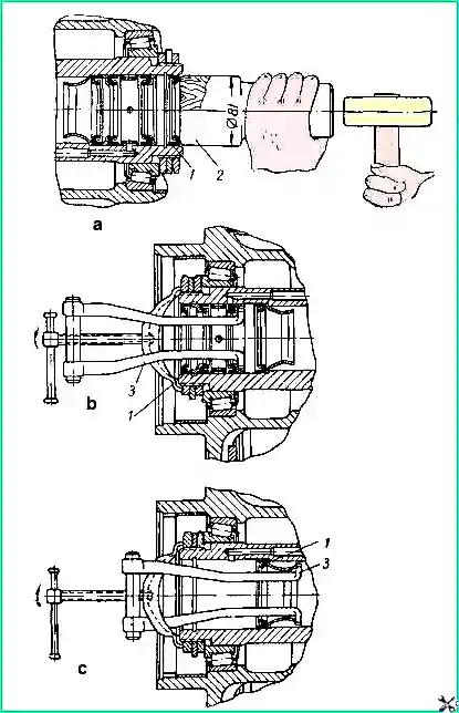
Mount the cuffs using a special mandrel (position a), which eliminates the possibility of damage when pressing them in.
Remove the cuffs with a special puller (position b and c) which is included in the tool kit.
If there is significant damage to the air pressure regulation system, inflate the tire using the hose included in the driver's tool kit, connecting it to the air bleed valve and alternately to the wheel valves.


