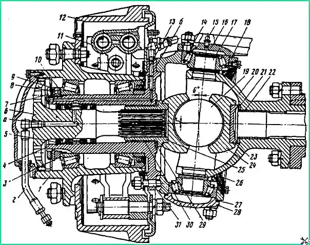
The design of the wheel part and the steering knuckle assembly of the front drive axle is shown in Fig. 1
Disassemble the steering knuckle assembly only when replacing the lubricant in the steering knuckle housing, when adjusting the kingpin bearings, and in the event of a malfunction (breakage of constant velocity joint parts, destruction of the kingpin bearing).
When disassembling the unit, you cannot remove the worn-in parts of the hinge. In addition, it is important to maintain the relative position of the hinge parts.
Disassembling the steering knuckle assembly
Close the wheel valves, remove the protective cover and disconnect the air supply hose 2 from the wheel valve, the wheel being removed.
Loosen the wheel nuts.
Raise the front of the car and install a stand under the front end of the frame.
Unscrew the wheel nuts and remove the wheel.
Disconnect the hose of the brake system, sealing system and tire inflation system.
Unscrew and unscrew the nut securing the ball pin of the steering linkage linkage, bipod linkage or power steering tip (if the right steering knuckle assembly is disassembled).
Use a puller to press out the ball pins.

Wheel part and steering knuckle: 1 - hub; 2 - air supply hose; 3 - bearing; 4 - rotary axle; 5 - block of air supply cuffs; 6 - front axle shaft; 7- lock nut; 8 - pin; 9 - lock washer; 10 - internal trunnion nut; 11 - wheel brake cylinder; 12 - brake drum; 13 - cuff; 14 - expansion sleeve; 15 - grease nipple; 16 - steering knuckle lever; 17 - kingpin; 18 - steering knuckle housing; 19 - hinge disk; 20 - ball joint; 21 - axle thrust washer; 22, 30 - bushings; 23 - internal axle shaft; 24 - hinge fist; 25 - outer axle fork; 26 - ball joint oil seal assembly; 27 - adjusting shims; 28 - bearing cover; 29 - support washer; 31 - hairpin; a - threaded hole for the axle puller; b - channel in the trunnion for air supply
Unscrew the bolts securing the hub cover, unscrew the air supply elbow from the axle shaft 6 and remove the hub cover together with the seal and the air supply hose.
Use a puller to remove axle shaft 6.
Bending the edge of the lock washer, unscrew the lock nut 7, remove the lock and lock washers.
Unscrew nut 10 and remove the wheel hub assembly with the brake drum.
Use a pry bar to remove the brake pad tension spring.
Unscrew the nuts securing the brake shield and steering axle 4.
Remove the brake shield assembly with brake pads, wheel cylinder 11, race, dust seal and washer.
Remove the steering pin from the studs of the steering knuckle housing.

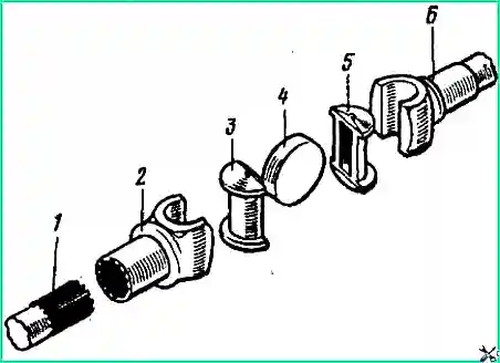
Remove the parts of the constant velocity joint (Fig. 2).
Use paint to mark the relative positions of the worn-in parts of the hinge.
Remove lubricant from the steering knuckle housing and the ball joint cavity.
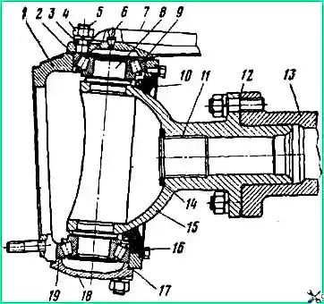
Unscrew the bolts securing the oil seal 10 (Fig. 3) of the ball joint and remove the oil seal.
Remove rubber plug 16 from the groove of the steering knuckle housing.
Unscrew the nut securing the lever 7 and, lightly tapping the lever with a hammer, remove the expansion cone bushings 3 and the lever with the gasket package 2 from the studs.
Unscrew the nuts securing the cover 18 and remove the cover together with the pack of adjusting shims 17.
Assemble the shim packs with lever 7 and cover 18.

Ball joint assembly: 1 - steering knuckle housing; 2, 17- shims; 3 - expansion sleeve; 4, 5 - nut and stud for securing the lever; 6 - grease fitting; 7- steering knuckle lever; 8 - kingpin; 9.19 - tapered roller bearings; 10 - ball joint oil seal assembly; 11 - bushing; 12 - sealing gasket; 13 - axle housing; 14 - axle thrust washer; 15 - ball joint: 16 - rubber plug: 18 - bearing cap
Press out the outer rings of bearings 9 and 19, using a puller, remove the inner rings of the bearings assembled with the rollers. Remove the steering knuckle housing.
If it is necessary to replace the oil seal 10, unscrew the nuts securing the ball joint 15 and use a spudger to remove it using the recesses of the ball joint flange.
Assemble the steering knuckle assembly in the reverse order of disassembly.
Before installing the constant velocity joint and pin bearings, be sure to lubricate the mating surfaces of the parts.
The sealing gaskets of the ball joint, oil seal and steering axle, the mating surfaces of the steering knuckle housing 1, lever 7 and cover 18 must be lubricated with a thin layer of sealing lubricant, the ball joint neck under the axle housing - with graphite lubricant.
Before installing the inspection hole plug or steering knuckle housing studs, also apply sealing lubricant to the threaded surface of the holes.

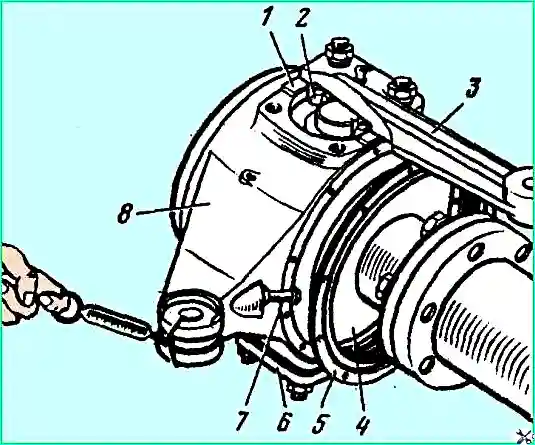
Checking the adjustment of the pivot bearings: 1 - shims; 2 - tapered roller bearing; 3 - steering knuckle lever; 4 - ball joint; 5 - oil seal cover; 6 - bearing cover; 7 - thrust bolt; 8 - steering knuckle housing
Before installing and fastening the ball joint seal parts (oil seal race, collar, sealing and spacer rings, oil seal cover), adjust the preload of the pin bearings.
Adjust the bearings by changing the thickness of the shim packs 2 and 17.
The set of adjusting shims produced by the factory consists of four standard sizes with a thickness of 0.5; 0.22; 0.1 and 0.05 mm.
Each package of adjusting shims installed under lever 7 and cover 18 must contain at least two shims 0.05 mm thick located on both sides of the package.
The amount of torque required to smoothly rotate the steering knuckle body should be 2.2-2.7 kgf/m, which corresponds to a force of 8-10 kgf applied to the end of the steering linkage lever (cast integrally with the knuckle body).
The force required to smoothly turn the fist is determined using a dynamometer (Fig. 4).
If the force value is outside the specified limits, select adjusting shims 2 and 17 (see Fig. 3) to achieve the required turning force.
After adjustment, the thickness of the shim packs under the lever and the cover should not differ by more than 0.05 mm.
When installing the ball joint seal seal, make sure that the spring does not fall out of the seal groove.
After installing the oil seal cover, the recesses under the surface of the ball joint should be located along an axis perpendicular to the axis of the pins.
When assembling, install the constant velocity joint parts in accordance with the marks made during disassembly.
Before installation, soak the dust seal with transmission lubricant.
Having installed the hub assembly with the brake drum, adjust the hub bearings.
If necessary, adjust the gap between the brake pads and the drum.
After assembly, fill the steering knuckle housing with lubricant through the filler hole (which is also a control hole).


