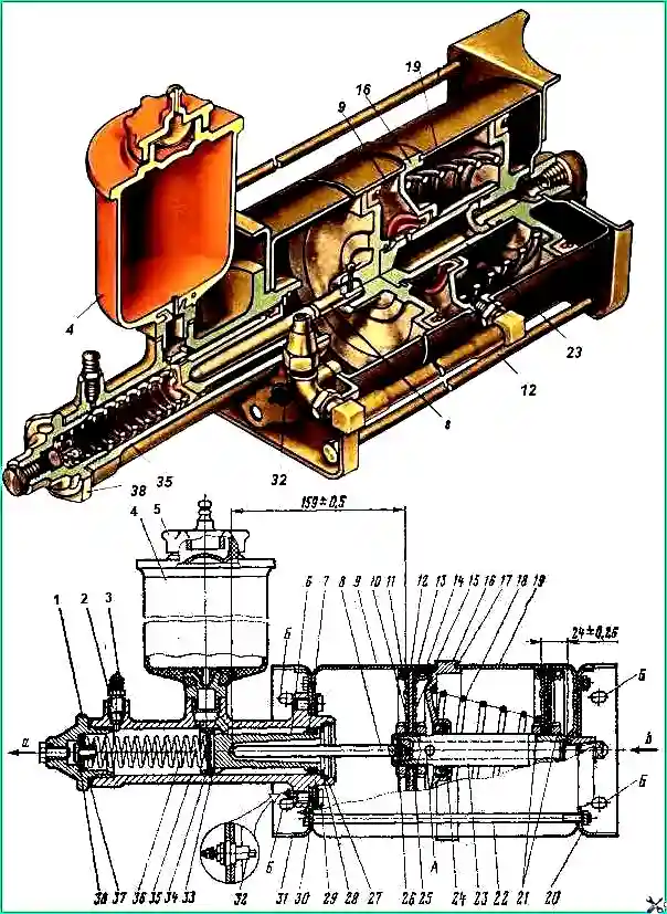
The pneumatic brake booster (Fig. 1) is designed to convert the energy of compressed air into the required pressure of the working fluid in the hydraulic part of the brake drive
To increase the reliability of the brakes, Ural vehicles are equipped with two power boosters, which are installed on the outside of the left side member under the cab.
The front pneumatic booster operates the service brakes of the front and middle axle wheels, the rear - the service brakes of the rear axle wheels.
When you press the brake pedal, the valve in the brake valve opens and air flows through the pipeline under the pistons of the pneumatic booster.
Under air pressure, the rod with the pistons moves and, through a pusher, acts on the piston of the main brake cylinder, which displaces fluid into the brake line.
When the brakes are released, the air from the pneumatic booster escapes into the atmosphere through the brake valve.
The pistons of the main brake cylinder and pneumatic booster return to their original position under the action of springs.
Remove pneumatic boosters from the vehicle and disassemble them only for maintenance and troubleshooting (replacing worn cuffs, etc.).
When removing the pneumatic boosters from the vehicle, disconnect the brake and sealing system pipelines from them and the main brake cylinders, as well as the wires from the “Brake” warning light sensors.
Unscrew the bolts attaching to the frame side member and remove the pneumatic amplifiers.
Disassembling pneumatic amplifiers
Drain the brake fluid, unscrew and remove reservoir 4, unscrew the nuts, remove the ties 22 and the rear pneumatic cylinder 19.
Remove the hose, pistons assembled with rod 23, spacer 16 and pusher 8.
Unlock and unscrew the bolts 29, remove the locking plates 30, the front cylinder of the air booster 9 assembled with the cover 31 and the gasket.
Remove the retaining ring 27, washer 28 and remove the piston 6 assembled with the outer seal 7. Remove the ring 33, the inner sealing collar 34 and the spring 36 assembled with the check valve 38.
When disassembling, it is not recommended to unscrew plug 1.
Unscrew the nuts 21 on the rod, remove the pistons 12 assembled, spacer 16 assembled with cuff 24 and o-rings 17.
Knock pin 26 out of the rod and disconnect rod 23 from pusher 8.

Parts of the main brake cylinder must be washed in alcohol or brake fluid, parts of the pneumatic booster - in kerosene or gasoline.
Data for monitoring the main dimensions of the parts of the pneumatic booster and the main brake cylinder are given in the table.
Table 1.
Pneumatic booster cylinders front and rear. Inner diameter:
- - nominal size - 150+0.230 mm;
- - permissible size - 150.50 mm
Brake master cylinder. Inner diameter:
- - nominal size - 40+0.030 mm;
- - permissible size - 40.07 mm
Piston of the main brake cylinder. Outer diameter:
- - nominal size - 40-0.025 mm;
- - permissible size - 39.90 mm
If the cuffs in the spacer, as well as the piston cuffs of the main brake cylinder and the pneumatic booster are worn out or mechanically damaged, replace them. The cylinder mirror must be free of corrosion and marks.
There should be no chips or cracks on the main brake cylinder, and no dents on the pneumatic booster cylinders.
Assemble the pneumatic booster in the reverse order of disassembly, and it is necessary to fulfill a number of the following mandatory requirements:
- - apply lubricant CIATIM-201 to the working surface of pneumatic cylinders 9, 19 (see Fig. 1), rod 23, cuff 24 and 13. Felt rings of 11 pistons - soak in spindle oil;
- assembly pneumatic booster pistons in a ring with a diameter of 150 +0З mm;
- - when assembling rod 23 with pistons 12, spacer 16 and pusher 8, it is necessary to maintain the dimensions indicated in Fig. 1;
- - install a rubber sealing ring 25 between the cuff support ring 15 and piston 12;
- - install the gasket and bolts 29 securing the master brake cylinder to the front cylinder of the air booster, as well as nuts 21 securing the pistons to the rod using sealing lubricant;
- - install the spacer relative to the front cylinder so that the fittings connecting the outlet holes are on the same straight line;
- - install the back cover 20 relative to the front 31 so that the surfaces with holes “B” are in the same plane.
The assembled pneumatic booster must be checked for leaks with an air pressure of 4.0-4.5 kgf/cm².
In this case, the main brake cylinder must create a fluid pressure of 100-112 kgf/cm².
Leaks of liquid and air are not allowed.
Install pneumatic boosters on the car, connect the pipelines and bleed the hydraulic system.


