The winch (Fig. 2) is designed for self-pulling, as well as for pulling cars and trailers in difficult areas
It consists of a worm gearbox, a drum with a cable attached to it and a cable guide.
The gearbox mechanism consists of a globoid pair with a gear ratio of 31:1.
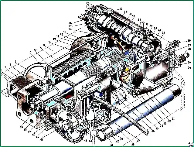
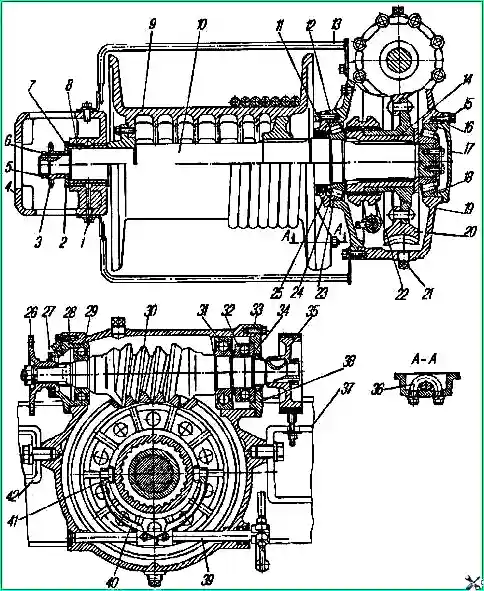
The worm wheel 20 is riveted to the hub, which can be connected to the drum shaft 10 using a movable coupling 22.
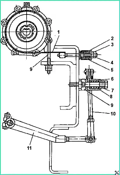
An automatic band brake 1 is installed on the gearbox worm (Fig. 3), which prevents spontaneous rotation of the winch drum and unwinding of the cable when the vehicle’s clutch is disengaged and when the safety pin is cut off.
Adjust the brake with the drive running in reverse gear and the movable drum clutch disengaged.
If within 1 - 3 minutes the brake heats up above the temperature that the hand can withstand (about 60 ° C), unscrew nut 3 and lock nut 4 securing the band by two or three turns.
Adjusting the winch gearbox
Adjust the gearbox bearings when axial clearances appear in them, as well as when installing a new worm pair.
Adjust the bearings only if tightening the bearing cap bolts does not eliminate the axial play.
Bearings must be adjusted with tension.
The torque required to rotate the gearbox worm in bearings 29, 31 and 32 (see Fig. 2) should be 1.0-2.5 Nm (0.1-025 kgf.m).
If the shaft rotates too freely or has axial play, remove a portion of shims 28 and 33 of equal thickness from under the front and rear bearing caps.
If a torque of more than 2.5 Nm (0.25 kgf.m) is required to rotate the shaft, add spacers of equal thickness under the covers.
When checking the rotation torque of the worm shaft, the bolts securing the covers must be tightened to capacity.
The number of spacers under the rear and front covers after adjustment should be approximately identical, which facilitates subsequent adjustment of the engagement of the worm pair.
Adjust the tapered bearings of the worm wheel shaft by changing the number of shims 16 and 24 under the bearing caps.
Check the preload of the worm wheel shaft bearings in engagement with the worm.
The torque required to rotate the worm wheel shaft in the bearings should be 3-6 Nm (0.3-0.6 kgf.m).
After adjusting the bearings, check that the worm pair is properly engaged with the paint using the contact patch of the teeth.
In a correctly adjusted pair, the contact patch of the working surface of the wheel tooth without load should be located in its middle and be at least 5 mm in width and 2/3 in height of the tooth.
The location of the contact patch along the height of the tooth is changed by the corresponding movement of the worm 30 in the axial direction using spacers.
To shift the contact patch to the tooth stem, remove some of the gaskets 28 from under the cover 27 on the flange side; to shift the contact patch to the tooth head, add spacers.
In this case, accordingly, change the number of shims 33 under the cover 37 on the brake side so that the total thickness of the shims on both sides is maintained.
The displacement of the contact patch along the width of the wheel tooth is achieved by axial movement of the worm wheel in the same direction in which the patch is displaced.
The globoid worm pair can only work well if the gearing is properly adjusted.
Improper adjustment causes strong heating of the pair and rapid wear of the worm wheel teeth.
Winch drive

Power from the transfer case through an additional power take-off box to the winch gearbox is transmitted by three cardan shafts.
On the front driveshaft, to protect the winch parts from overload, a safety pin 2 is installed (Fig. 3), which is cut off when the load is higher than permissible.
All cardan joints are identical in design and are identical to the joints of the GAZ-53A car.

The intermediate driveshaft is mounted on two supports.
To compensate for inaccuracies during installation, sliding forks 7 of the front and rear shafts are installed on the splined ends of the intermediate propeller shaft.
Lubricant in the spline joint is retained by O-rings 8.
To reduce the uneven rotation of the winch gearbox worm, the drive shafts are installed so that the axes of the holes for the bearings in the sliding forks of the front 4 (see Fig. 5) and rear 6 shafts lie in the same plane.
Cable laying machine
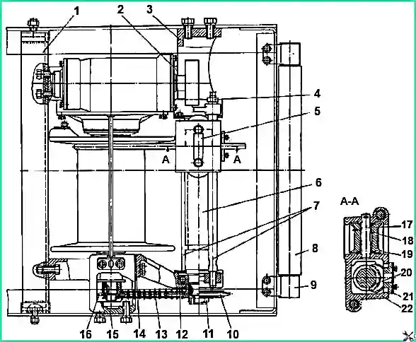
The winch is equipped with a cable layer (Fig. 4), which ensures correct laying of the cable on the drum at angles of deviation from the vehicle axis not exceeding 15°.
The cable is secured to the drum with a bracket; it extends only backwards.
The housing 22 of the guide roller holder lays the cable, making a reciprocating movement along the lead screw 6 and along two guide rollers 7.
A screw with left and right threads, mounted on two bearings, is driven by a chain transmission from the drum shaft through the drive 16 and driven 10 sprockets.
The chain tension is adjusted by spacers 2 and 14; chain slack amount 3—10 mm.
The axial force from the lead screw 6 is transmitted to the body of the guide roller holder through the lead screw 20.
The block is installed in the housing of the guide roller holder and secured with cover 21.
Guide rollers 19 are mounted on polyamide bushings 18 and rotate on pins 17, which are fixed by a locking plate 5.
Rules for using the winch
Before operating the winch, make sure that the drive for turning the winch drum on and off is working correctly, as well as that the cable is wound correctly and securely fastened.
With a correctly adjusted drive, the length of rod 10 (see Fig. 3) along the axes of the holes of the adjusting forks should be 228-232 mm.
If it is difficult to turn on the winch drum in the cold season, it is necessary to warm up the winch gearbox at idle for 3-5 minutes.
Do not use the winch cable to tow a car or trailer, or at angles of deviation from the vehicle axis exceeding 15°.
To turn on the winch:
- - set the transfer case and gearbox levers to the neutral position;
- - using a 30mm wrench, place the movable clutch lever in the upper (on) position when forcing the cable out.
When manually unwinding the cable, the movable clutch lever must be in the lower (off) position;
- - release the stopper and move the auxiliary power take-off lever forward until it stops;
- - having engaged first or second gear, extend the cable to the required length; select the slack of the cable manually.
Before starting to pull up, there must be at least three to four turns of cable on the drum;
- - engage reverse gear to pull up the load;
- - when pulling the car out, engage the transfer case downshift and reverse gear of the gearbox.
Increase the engine crankshaft rotation speed smoothly.
A sharp increase in engine speed does not increase the traction force on the cable, but can cause shearing of the safety pin.
After cutting the pin, immediately disengage the clutch and move the gear lever to neutral, otherwise the shaft may become stuck in the flange.
Replace the cut pin with a new one.
Do not use bolts or other parts in place of the safety pin.
In operation, it is difficult to determine the force on the cable, so before using the winch, approximately determine the advisability of using the block, based on specific conditions.
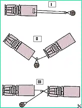
The use of a winch using a block is shown in Fig. 7. When using a block without a hook, use a tow rope attached to the vehicle.
If the block is used to increase the traction force during self-pulling (I position), then it is secured with a towing rope to the object selected as a support, and the hook of the winch cable to the hook of the towing device.
If the block is used to change the direction of traction when pulling out another car (position II), then it is secured with a tow rope to an object serving as a support, and the hook of the winch cable is secured to the tow hook of the vehicle being pulled out.
If the block is used to increase the traction force when pulling out another car (position III), then it is secured to the towing hook or towing cable draped over the towing hooks of the vehicle being pulled out, and the winch cable hook to the stationary object using the second tow rope.
It is allowed to fasten the winch cable directly to a stationary object, while the hook is hooked onto a pre-tightened cable.
To avoid overheating of the winch gearbox, do not pull the load using the full length of the cable more than three times in a row at or near maximum load.
Maintenance
When servicing the winch after 10 ÷ 15 pull-ups or once a year during “Maintenance”, replace the oil in its gearbox (Fig. 8).
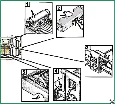
To do this, drain the oil from the gearbox and fill it with 7.5 liters of engine oil through the filling plug.
Lubricate the winch drum shaft bearing with litol-24 (Fig. 2).
Clean the winch from dirt and lubricate the lead screw and chain of the wasp layer, check the winch fastening and the condition of the cardan drive to it.
Winch lubrication points:
- 1 – winch gearbox, once every two years 7.5 liters of hypoid oil;
- 2 – towbar bushings, two lubrication points, after 4000 km, Litol-24 lubricant;
- 3 – lubricate the working surfaces of the winch cable guide lead screw with graphite grease after each use of the winch. Lubricate the roller bushings and the cavities of the housing of the winch cable guide roller holder with graphite grease during disassembly;
- 4 – lubricate the chain drive of the winch cable guide once a year with USsA graphite grease;
- 5 – winch drum shaft sliding bearing, lubricate once a year during seasonal maintenance


