The tractors are equipped with a fifth-wheel coupling device with a locking hole in the grips with a diameter of 50.8 mm. The device is designed to articulate a tractor with a semi-trailer having a standard coupling kingpin.
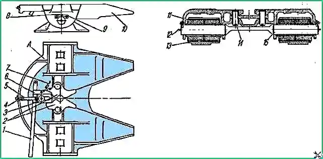
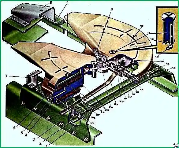
Saddle 10 (Fig. 1), on which the semi-trailer rests, swings in the longitudinal and transverse planes. In the longitudinal direction - on axes 15, in the transverse direction - due to deformation of the rubber of the hinges 11.

The coupling of the saddle with the semi-trailer kingpin is carried out by two grippers 2 of the coupling mechanism.
The grips are installed on fingers 14 and, rotating on them, cover the kingpin.
The grips are held in the closed position by the locking fist 3 under the action of the spring 5 installed on the locking fist rod.
When coupling has occurred, self-release fuse 4 takes a vertical position.
To release, turn the self-release safety device to the side and use handle 1 to move the locking fist 3 to the extreme forward position.
Latch 6, pulled back by spring 7, fixes the fist in the forward position.
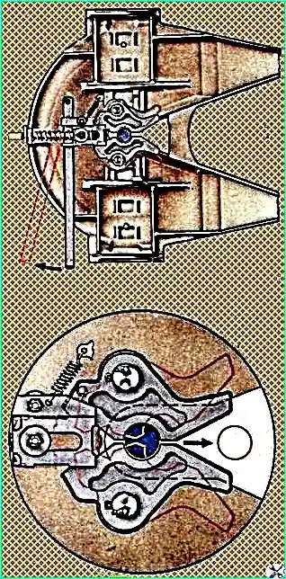
When the tractor leaves, the semi-trailer's kingpin spreads the grips of the coupling mechanism and disengages from them.
At the same time, the left grip with the pin on it turns the latch, which allows the locking fist to move back until it stops at the ends of the grips, which are held in the open position.
With this position of the mechanisms, the saddle is prepared for automatic coupling with a semi-trailer.
When coupling, the semi-trailer's kingpin, moving, turns the grips and forces them to close.
The locking fist, sliding along the ends, enters the groove of the grippers, closing them automatically.
The fifth wheel coupling device is attached to the tractor frame through brackets 13, subframe and bars. To facilitate coupling of the tractor with the semi-trailer, a rollover slide is installed behind the fifth wheel.

Coupling and uncoupling
Before coupling, make sure that the saddle device and its fastening are in good condition, the saddle and slide guides are not dirty and there are no foreign objects on them; if necessary, clean the upper surface of the saddle from contaminated grease and lubricate it with a thin layer of fresh one.
Securely brake the semi-trailer with the parking brake and install it on the support device so that the supporting plane of the semi-trailer is from the ground level at the same level as the tractor saddle or slightly below it.
Couple and uncouple on a flat, horizontal platform with a hard surface.

In this case, the longitudinal axes of the tractor and semi-trailer must be located in one straight line.
Coupling order:
- 1. Move the self-release safety device aside and place the grip lock handle in the forward extreme position.
- 2. Bring the tractor in reverse at low speed towards the semi-trailer so that the semi-trailer's king pin falls between the slide guides and engages the saddle grips until it stops. In this case, the coupling should occur automatically.
- 3. Apply the parking brake to the tractor.
- 4. Make sure that the grip lock handle is in the rear end position and that the self-release safety device is positioned vertically down and locks the locking knuckle rod.
- 5. Raise the semi-trailer support device to its highest position and securely fasten it.
- 6. Connect the connecting cable to the power socket semi-trailer wiring cable.
- 7. Connect the connecting hose of the pneumatic drive of the tractor brakes to the connecting head of the semi-trailer.
- 8. Open the valves of the pneumatic brake drive on the tractor and floor trailer, placing their handles parallel to the longitudinal axis of the valve.
- 9. Release the parking brake of the semi-trailer.
- 10. Move the road train a certain distance, make sure that the coupling is in good condition, the brakes and electrical devices of the semi-trailer are working properly.
Uncoupling order:
- 1. Apply the parking brake to the semi-trailer.
- 2. Lower the semi-trailer support device until it stops on the road surface, unloading some of the tractor springs.
If forced uncoupling on non-compacted soil, place chocks under the semi-trailer support device.
- 3. Close the isolation valve of the tractor pneumatic system and the control valve with the brakes of the semi-trailer, placing their handles perpendicular to the longitudinal axis of the crane.
- Disconnect the connecting heads of the pneumatic brake drive and close the protective covers of the heads.
Attach the connecting head with the hose to the tractor platform.
- 4. Unplug the connecting cable from the electrical wiring and the socket and secure the cable to the tractor platform.
- 5. Move the saddle self-release safety device aside and move the grip lock handle to the forward extreme position.
- 6. Engage first gear and move the tractor forward at low speed until the semi-trailer is completely disengaged.
When installing a fifth wheel on a vehicle, before tightening the bolts and stepladders, it is necessary to use shims to ensure a gap of 2 - 3 mm between the frame and subframe brackets.
The tightening torque of the saddle device must be 10 – 14 kgf/m, for bolts M14 – 8 ÷ 10 kgf/m.


