The main drive of the driving axles is shown in Figure 1.
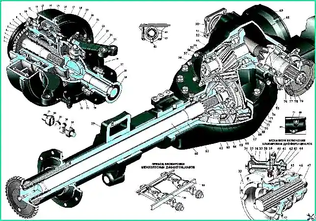
Drive axle with interwheel differential locks: 1 – rotary axle; 2 – cuffs of the tire inflation system; 3 – outer axle shaft; 4 – pin; 5 – lock nut; 6 – lock washer; 7 – wheel bearing nut; 8 – wheel hub; 9 – wheel nut; 10 – hub stud; 11 – brake drum; 12 – wheel brake cylinder; 13 – brake cylinder spring; 14 – bypass valve; 15 – brake fluid supply fitting; 16 – air supply fitting; 17, 29, 76 – cuffs; 18 – steering knuckle body; 19 – outer axle fork; 20 – steering knuckle lever; 21 – steering knuckle pin; 22, 54, 56, 74 – adjusting gaskets; 23 – ball joint seal; 24 – hinge fist; 25 – hinge disk; 26 – ball joint; 27 – front axle axle housing; 28 – internal axle shaft; 30 – bronze bushing; 31, 52, 64, 67 – support washers; 32 – cover; 33, 66 – differential cup; 34 – switching chamber cover; 35 – diaphragm; 36 – housing of the locking mechanism; 37 – spring; 38 – rod; 39 – gasket; 40 – sensor; 41, 43 – fingers; 42 – bracket; 44 – limiter; 45 – fork; 46 – coupling; 47, 60 – axle shafts; 48 – gearbox housing; 49 – gearbox housing cover; 50, 79 – flanges; 51 – key; 53 – driving cylindrical gear; 55 – cup of bearings; 57 – glass lid; 58 – pressure washer; 59 – spring support bracket; 61 – axle housing; 62 – adjusting nut; 63 – differential bearing cover; 65 – axle gear; 68 – satellite; 69 – driven cylindrical gear; 70 – differential crosspiece; 71 – axle housing; 72 – crankcase gasket; 73 – driven bevel gear; 75 – bevel drive gear; 77 – flange reflector; 78 – gearbox through shaft; 80 – filler plug; 81 – drain plug; 82 – locking plate; 83 – locking mechanism
One of the characteristic signs indicating the need to disassemble and adjust the gearbox is increased noise when the vehicle is moving.
Causes of increased noise:
- - displacement of the contact patch in the meshing of bevel gears as a result of improper adjustment of the tapered bearings;
- - scuffing and chipping of gear teeth, wear of bearings, as well as insufficient oil level in the axle housing.
The driving axles of the vehicle are of the through type, with an overhead final drive.
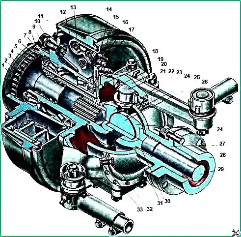
1 - Rotating pin; 2 - oil seals for the tire inflation system; 3 - outer axle shaft; 4 - pin, 5 - outer axle nut, 6 - lock washer, 7 - inner axle nut, 8 - wheel hub, 9 - wheel nut, 10 - hub stud, 11 - brake drum, 12 - wheel brake cylinder, 13 - spring brake cylinder, 14 - bypass valve, 15 - brake fluid supply fitting, 16 - air supply fitting, 17 - dust seals, 18 - steering knuckle housing, 19 - oil seal, 20 - outer axle fork, 21 - steering knuckle lever, 22 - steering knuckle pin, 23 - shims, 24 - hinge knuckle, 25 - ball joint seal, 26 - hinge disk, 27 - ball joint, 28 - front axle casing, 29 - inner axle shaft, 30 - bronze bushing, 31 - support washer , 32 - rotation limiter bolt, 33 - bolt lock nut.
The main drive of the bridge is double, consisting of a pair of bevel gears 1 and 14 (Fig. 3) with spiral teeth and a pair of cylindrical gears 4 and 29 with oblique teeth.
A symmetrical bevel differential with four pinions is bolted to the driven spur gear.
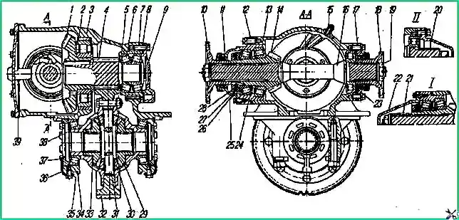
Main drive of the bridge: 1 - driven bevel gear; 2.23 - cylindrical roller bearings; 3 - main gear housing; 4 - cylindrical drive gear; 5 - cup of bearings; 6 - tapered roller bearing; 7,8,12 - adjusting gaskets; 9 - bearing cup cover; 10 - front axle drive flange; 11 - cuff; 13 - cup of bearings of the drive bevel gear; 14 - bevel drive gear; 15 - breather; 16 - drive gear shaft, 17 - gasket; 18 - rear axle drive flange; 19 - flange nut; 20 - rear bearing cover; 21 - spacer sleeve; 22 - front bearing cover; 24 - washer radjusting; 25 - nut: 26 - lock washer; 27 - lock washer; 28 - lock nut; 29 - semi-axial gear; 30 - differential satellite; 31 - differential crosspiece; 32 - cylindrical driven gear; 33 - support washer; 34 - differential bearing cover; 35 - locking plate; 36 - key plate; 37 - differential bearing adjusting nut; 38 - differential cup; 39 - crankcase cover; I - for the front axle; II - for rear axle
Depending on the technical requirements for the car, the main gears have gear ratios of 7.32; 6.7; 8.9 and 8.05.
To distinguish the main gears, they are marked with plates indicating the gear ratio, installed under the bolt securing the bearing cup cover of the drive spur gear.
Final drives with a gear ratio of 8.9 do not have marking plates.
The main gears are distinguished by marks on the drive and driven cylindrical gears (see table)
Table 1.
Gear ratio 6.7:
- - marks on the end of the drive spur gear on the installation side of the bevel gear - two drillings ∅ 10 mm at a distance of 12 mm from the edge to a depth of 2 mm;
- - mark on the driven spur gear - chamfers on both sides under the gear crown
Gear ratio 7.32:
- - marks on the end of the drive cylindrical gear on the installation side of the bevel gear - drilling ∅ 10 mm to a depth of 2 mm;
- - mark on the driven spur gear - chamfer under the ring gear
Gear ratio 8.05
- - marks on the end of the drive cylindrical gear on the installation side of the bevel gear - cylindrical groove ∅ 52 mm;
- - mark on the driven spur gear - Mark at the end ∅ 290 mm
Gear ratio 8.9:
- - marks on the end of the drive cylindrical gear on the installation side of the bevel gear - No
- - mark on the driven spur gear - No
The main gear is installed on the axle housing 10 (Fig. 4) through a 0.8 mm thick paronite gasket 9 and secured with eleven bolts and two studs.
Eleven bolts and studs are installed externally, and two bolts are installed in the cavity of the bevel gears.
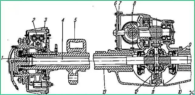
Access to the internal bolts is only possible after removing the side cover 6.
Spring washers are installed under the outer bolts and nuts of the studs.
The internal bolts are secured with wire.
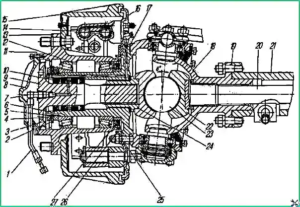
Drive to the steered wheels of the front drive axle: 1 - air supply hose; 2 - lock washer; 3 - retaining ring; 4 - lock nut; 5 - nut; 6 - axle; 7 - air supply elbow; 8 - wheel hub cover; 9 - outer axle shaft; 10 - cuff block; 11,17,19 - sealing gaskets; 12 - bearing; 13 - hub; 14 - wheel brake cylinder; 15 - brake drum; 16 - brake shield; 18 - ball support; .20 - internal axle shaft; 21 - axle housing; 22 - hinge fist; 23 - hinge disk; 24 - outer axle fork; 25 - hairpin; 26 - reflector; 27 - cuff
The gears and bearings of the main gear are lubricated with oil poured into the axle housing and the main gear housing to the level of the inspection hole.
The oil is picked up by the gears, splashed and through roller bearing 2 (see Fig. 3) enters the cavity of the bevel gears of the main gear housing, from where it flows into the axle housing.
The bearings of the drive bevel gear are lubricated with oil from the cavity of the bevel gears, which is fed into the bearing cup through a pocket on the crankcase cover and the oil supply fitting.
The main drives of the front and rear axles differ from the main drive of the middle axle by drive flanges.
A bushing 21 with a cover 22 is installed on the front end of the drive gear shaft of the front axle, and a flange 18 is installed on the rear end.
The main gear of the rear axle has one flange on the drive bevel gear side.
At the opposite end of the drive gear shaft, splines may not be made.
The housings of 10 (see Fig. 4) axles are combined, consisting of a cast middle part and tubular axle housings pressed into it.
They are completely unloaded, the connection between the axle shaft and the hub is splined.
The front axle of the car is driven and steered. The design of the front drive axle pivot assembly is shown in Fig. 5.
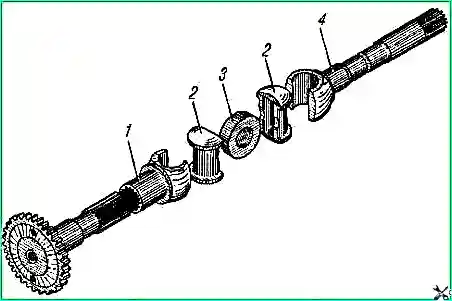
Torque to the front drive wheels is transmitted through axle shafts and constant velocity joints (Fig. 6).
For reliable and durable operation of drive axles, use oils according to the chemical chart and maintain the required level in the crankcases.
To replace the lubricant in the hinges of the front axle axles, remove the wheel, brake drum with hub, brake shield, and steering axle. Remove grease and wash the constant velocity joint parts.
Regularly check the tightening of the bolts securing the final drive to the axle housing.
Loosening the bolts causes the crankcase to bend.
Changing the oil in the drive axle housings and checking its level
Clean the drive axle housing from dust and dirt.
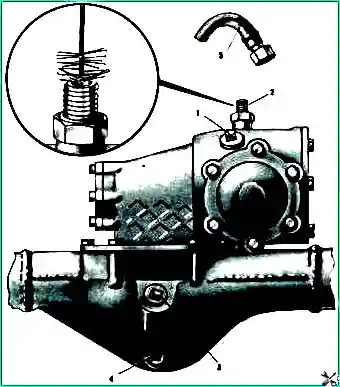
Unscrew plug 3 (Fig. 7) of the control hole and drain plug 4 in the crankcase, drain the oil (it is advisable to drain it immediately after stopping the car, when it is still warm).
Tighten the drain plug. Unscrew hose 5 from fitting 2 of the sealing system, clean it with a wire brush and screw it back.
Rinse the axle housing by pouring 1.5-2 liters of low-viscosity oil into it.
Drain the low-viscosity oil and fill the crankcase with 13.5 liters of clean transmission oil TSp-15k (MT-16p).
The oil should be changed one by one in all drive axles.
Check the oil level in the drive axle by unscrewing the inspection plug.
The oil should be level with its lower edge.
The filler hole, closed with plug 1, is used when filling the axle with oil after changing bevel gears.
Check that the connections are tight and that there are no oil leaks.
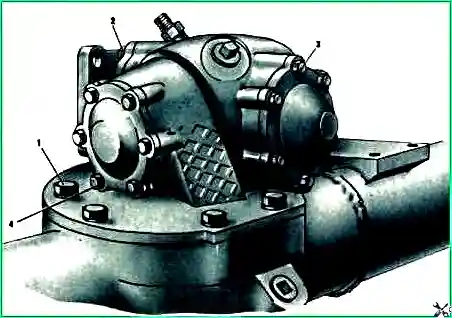
Tighten bolts 1 (Fig. 8) securing the gearbox, bolts 2 and 3 of the drive shaft covers and bolts 4 of the main gear bearing cups. There should be no traces of oil leakage on the surface of the crankcase and at the connectors.
Lubricating the hinges of the front axle axle shafts and the lower bearings of the king pins
Unscrew plug 1 (Fig. 9) of the filler hole of the steering knuckle housing and check for the presence of lubricant. It should be level with the filler hole.
If the level is insufficient, add a heated mixture consisting of 50% AM (cardan) grease and 50% TSp-15k and fill it into the steering knuckle housing to the specified level.
Tighten the cap.
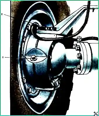
To replace the lubricant in the constant velocity joints of the front drive axle, disassemble the joints, remove the old lubricant, and wash the joint parts.
Place fresh lubricant directly inside the ball joints.
Lubricate the upper bearings of the pins through oiler 2 using a syringe press.


