The Ural-4320 and its modifications are equipped with a mechanical two-stage transfer case (Fig. 1) with an asymmetrical center differential
During the operation of the vehicle, the transfer case is periodically and routinely removed from the vehicle to inspect and adjust the axial play of the primary and intermediate shafts. It is advisable to eliminate the noticed malfunctions at the same time.
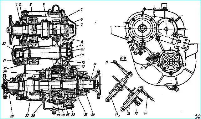
The design of the transfer case allows the input shaft with gears and the drive shafts of the front and rear axles to be removed from the crankcase without completely disassembling it.
The rear axle drive shaft can be removed as an assembly with the differential.
Malfunctions such as leakage of lubricant, loosening of the nuts securing the flanges on the shafts can be eliminated without removing the transfer case from the vehicle.
Elimination of such malfunctions as random shutdown of gears (wear of the splines of the gearshift carriage and the input shaft) or differential locking (wear of the splines of the differential lock clutch and the front axle drive shaft), breakdown, improper fit of parts, as well as adjustment work within the scope of technical maintenance is performed on the transfer case removed from the vehicle and partially disassembled.
The need to completely disassemble the transfer case occurs rarely and, as a rule, after long-term use of the vehicle.
Lubricant leaks should be detected by inspection and eliminated by tightening plugs, bearing cap bolts, or replacing gaskets and seals.
Arbitrary gear shifting and differential locking can be detected when the vehicle is driving with a variable load in difficult road conditions. In this case, the transfer case control levers move randomly:
- - gear shift lever towards neutral position;
- - differential lock lever in the direction of disabling the lock.
With increased wear, scuffing and breakage of transfer case parts, the operating noise changes, and extraneous knocking noises may appear when the vehicle is driven under normal road conditions.
Drivers with operating experience and mechanics usually detect these malfunctions by ear.
Removing the transfer case
It is more convenient to remove the transfer case if the car is installed on an inspection ditch in a room equipped with a lifting device.
To dismantle the transfer case from Ural-4320, -4420 and -44202 vehicles, lower the folding bracket of the spare wheel holder and remove the wheel.
Remove the driveshaft of the middle axle drive, disconnect the flanges of the driveshafts of the intermediate, front axle drive and front winch drive from the flanges of the transfer case and the additional power collection box.
Disconnect the wires from the speedometer sensor.
Undo the cotter pins and remove the pins, disconnect the rear ends of the control rods for the transfer box, additional power take-off box and parking brake.
Unscrew the sealing tube from fitting 11.
Move the disconnected ends of the driveshafts and control rods of the transfer case, additional power take-off and parking brake to the side and secure them to the vehicle frame.
Attach the lifting device to the bracket on cover 4 of the top hatch of the transfer case and lightly tighten the slings of the lifting device.
Unscrew and unscrew the nuts of the studs securing the transfer case to the brackets, remove the cushions and washers, carefully lower the box onto the trolley and remove it from under the car frame.
Disassembling the transfer case
First, disassemble the transfer case into large units, and then these units into individual parts.
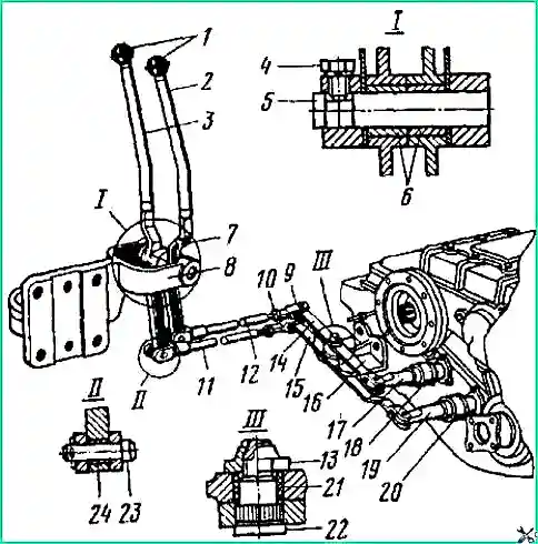
It is more convenient to begin complete disassembly of the transfer case by disassembling the control mechanism. To do this, unpin and remove the fingers, disconnect the leads 14, 15 (Fig. 4) from the rods 17, 19.
Unlock and unscrew the nuts 13 securing the arms to the bracket 16, remove the arms and bushings 21 from the shafts 22.
Unscrew the plugs 19 (see fig.) and use a wire hook to remove the springs and balls from the housings 22 and 20 of the gear shift and differential locking mechanisms.
Unscrew the bolts, remove bracket 16 (see Fig. 2) and housings 18 and 20 of the fixing mechanisms.
To remove the input shaft 7 from the crankcase (see Fig. 1), unscrew the bolts and remove the cover 4 with the gasket and the lifting bracket.
Secure the input shaft through the top hatch. Undo the cotter pin and unscrew the front flange mounting nut, remove the washer and press the flange using a universal puller.
Unscrew the bolts and remove the front and rear input shaft bearing caps.
Remove the sealing and adjusting gaskets and secure them to the corresponding covers.
On Ural-4320 vehicles equipped with a winch, remove the additional power take-off box installed in place of the rear bearing cover.
Install a soft metal spacer between the top gear 3 and the rear wall of the crankcase 6.
Install a puller in place of the front bearing cover and press the input shaft assembly out of the crankcase (Fig. 3).
Through the upper hatch of the crankcase, remove the top gear 3 (see Fig. 1) with a bushing, support washer 2, inner ring of the front bearing 1, soft metal spacer and gear shift carriage 5.
Using a puller, press out the outer race of front bearing 1. Remove the parking brake.
To remove the intermediate shaft 29 and gears 16 and 28 (see Fig. 1), unscrew the bolts, remove the front and rear bearing caps, adjusters 9 and sealing gaskets.
Attach the gaskets to the corresponding covers.
Unscrew nut 12 of rear bearing 14, remove thrust washer 13.
Install a puller in place of the rear cover and press the intermediate shaft assembly out of the crankcase (Fig. 4).
Through the upper hatch, remove gears 28 and 16 (see Fig. 1) of high and low gears, spacer sleeve 15, inner ring of the rear bearing and gear fork assembly with rod 23.
Install the puller and press out the outer race of the rear bearing.
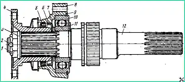
To remove the front axle drive shaft 27 unscrew the bearing cover bolts and, using light blows of a hammer on the flange, remove the shaft assembly (Fig. 5).
Remove the sealing gasket and secure it to the cover.
To remove shaft 24 (see Fig. 1) of the rear axle drive, unscrew the bolts securing the rear bearing cover.
Use light blows of a hammer to separate the cover from the crankcase.
Insert two screwdrivers into the gap formed between the crankcase and the cover, so as not to damage the gasket.
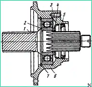
By rocking, remove the shaft (Fig. 6).
Remove the sealing gasket and attach it to the cover.
To remove the differential unscrew the bolts securing the rear differential bearing housing.
Use light blows to separate the rear bearing housing from the transfer case housing and secure it to the hook of the lifting device.
Remove the differential assembly from the crankcase. Unscrew rod 21 (see Fig. 1) and remove fork 18 together with differential lock clutch 26.
Remove the gasket and secure it to the rear bearing housing.
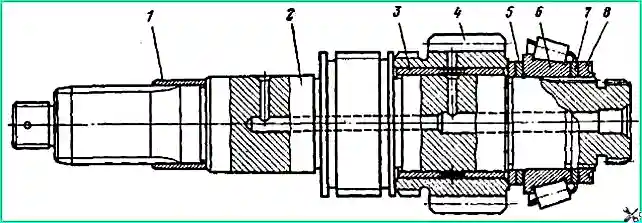
When completely disassembling the units, install the input shaft 2 (see Fig. 3) by the splined part in a vice.
Unscrew nut 8, remove lock washer 7.
Using a universal puller, compress the low gear gear 4 with the bushing 3, support washers 5 and the inner ring of the rear bearing 6 (1 - bushing).
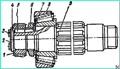
Install the intermediate shaft 9 (see Fig. 4) by the splined part in a vice, bend the antennae of the locking plate 2 and unscrew the bolts 3 securing gear 1 of the speedometer drive.
Remove lock plate 2, thrust washer 4, gear 1 and key 5.
Unscrew the nut 6 securing the bearing, remove the support washer 7 using a universal puller, and compress the inner ring of the bearing 8.
Install the front axle drive shaft (see Fig. 5) by the splined part in a vice.
Remove cotter pin 2 and unscrew nut 1, remove washer 3 and press flange 4 using a puller.
Use light blows on cover 8 to press it off bearing 10, remove oil sump ring 6 and thrust washer 7.
Remove the retaining ring 9 from the bearing and use a puller to press the bearing off the shaft 12, remove the thrust washer 11 (5 - cuff).
Disassemble the rear axle drive shaft using the same methods as disassembling the front axle drive shaft, after first removing the locking ring 7 (see Fig. 6).
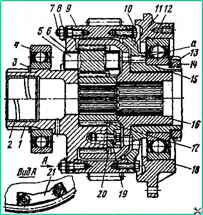
When disassembling the differential (Fig. 8), bend the ends of the locking plates 21 and unscrew the nuts 8 of the studs securing the front race 1 to the lower shaft gear 9.
Remove the locking plates and, with light blows, separate the front race assembly with washer 20, satellites 5 and sun gear 17 from the lower shaft gear. Remove the main gear 16 from the rear race 11.
Install the front cage in a vice, unscrew bolts 19, remove spring washers and separate washer 20 from the cage.
Remove the satellites and sun gear from the holder.
The front race and washer cannot be depersonalized during repairs, so after disassembly, combine them into a set.
Remove retaining ring 3 from the front race and press bearing 4 with a puller.
Bend the antenna of the lock washer 13, unscrew the nut 14 and remove the lock washer.
Using a drift with a diameter of 10 mm, with light blows of a hammer, through two holes in the rear race 11, press bearing 12 assembled with the crankcase 18 from the race.
Bend the ends of the locking plates and unscrew the bolts 10 securing the rear cage to the lower shaft gear, separate the cage from the gear.
Using a soft metal drift, press bearing 12 out of rear differential bearing housing 18.
Using a mandrel, press the seals out of the bearing caps.
Gears may have wear on the thickness of the teeth, chipping and pitting (rash in the form of small shells) of the cemented tooth surface, chips and cracks.
If there are defects such as cracks and chips at the ends of the teeth with a length of more than 5 mm, chipping with a total area of more than 8 mm2 or pitting covering more than 25% of the working surface of the tooth, the gears should be rejected.
Gears with small (0.5-1.0 mm) chips of the tooth ends can be used for further work. Sharp edges of chips, as well as burrs on the top of the tooth head, should be dulled and cleaned.
Control wear of teeth by thickness using a limit gauge or gear gauge.
Two methods are provided for checking the technical condition of the splines of parts: the first is by measurements using rollers, the second - based on the results of measuring the lateral gap between the splines in the connection of the worn part with the mating new one.
Assembling the transfer case is carried out in two steps: first, assemble the components, then assemble the box as a whole.
When assembling the box, first install fork 18 into the crankcase (see Fig. 1) together with coupling 26, rod 21 and gear fork assembled with rod 23, then install the remaining components and parts in the reverse order of disassembly.
When subassembling components and assembling the transfer case as a whole, consider the following.
Assemble the units to the completeness shown in Fig. 3—7.
Apply the lubricant used for filling into the crankcase onto the gear bushings of the input shaft of the gear and the journal of the shaft 7 (see Fig. 1).
Apply CIATIM-201 lubricant to the cuffs, the flange surfaces mating to them, the bearing journals of gear 10 and the teeth of gears 8 and 10.
Lubricate the sealing gaskets and threads in the through holes of the crankcase with a thin layer of sealing lubricant, and if this is not available, with any grease.
After subassembling the units, check the ease of rotation: shafts 24 and 27 in the bearing caps, low gear on shaft 7 and driven gear 10 in the intermediate shaft bearing cap.
Oil rings 6 (see Fig. 5) and 4 (see Fig. 6) differ from each other in the direction of cutting and are marked with the letters “P” and “3”, respectively.
When subassembling the assemblies, install the rings: marked “3” - on shaft 24 (see Fig. 1) of the rear axle drive; marked “P” - on shaft 27 of the front axle drive.
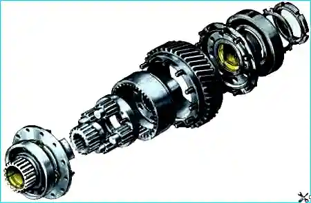
install flanges on shafts, cuffs and covers using mandrels. Install the lower shaft gear 9 (see Fig. 7) with the extended part of the hub (with studs) to the front race 1; sun gear 17 with the extended part of the hub to the rear race 11.
Install the differential locking clutch on the shaft so that the rounded ends of the splines are directed towards the engagement.
Tighten the main threaded connections of the parts with a torque wrench.
After tightening, lock the nuts and bolts of the critical threaded connections.
The friction of the nuts securing the bearings on the shafts and nuts 13 (see Fig. 2) for attaching the drivers must be carried out carefully, deforming the thin part of the nut into the groove of the shaft.
Adjusting the transfer case
When adjusting the transfer case, two types of work are performed to ensure that the normal axial play of the primary and intermediate shafts is checked and, if necessary, installed, as well as the normal position of the gearshift carriage and the differential lock clutch.
Axial play is estimated by the total axial movement of the shafts. When the shaft bearing nuts are tightened, the movement should be for the shafts: primary 0.15-0.20, intermediate 0.08-0.13 mm.
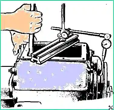
Measure axial play with an indicator, using a mounting blade to move the shafts (Fig. 10).
When adjusting the axial play of the intermediate shaft, rest the indicator leg against the end of one of the gears.
To avoid errors when measuring axial play, check the play before and after adjustment 2-3 times, first rotating the shafts before measurements.
If the axial movement is greater than normal, remove the adjusting shims for the input shaft from under the front bearing cover, and for the intermediate shaft - from under the rear bearing cover.
To ensure adjustment of the bearings under these covers, a package of adjusting shims is installed at the manufacturer, which contains at least four shims with a thickness of 0.05 mm and at least three with a thickness of 0.1 mm.
The position of the differential lock clutch is adjusted by rotating the rod.
When checking the correct position of the clutch, set the rod to the front fixed position and turn the front axle drive shaft by the flange.
If the clutch does not touch the splined end of the differential front race, then it is installed correctly. If the clutch touches the race, move it forward by rotating the rod clockwise.
Adjust the position of the gearshift carriage by selecting a package of shims 17 (see Fig. 1).
Three to six adjusting shims 0.2 mm thick are installed between the shift fork rod fixation housing and the transfer case housing.
The position of the coupling should be considered normal if, with the rod in a fixed neutral position, the difference in the free length of the input shaft splines on both sides of the coupling does not exceed 1 mm.
Transfer case test
After repair, carry out tests to check the quality of assembly and adjustment of the transfer case.
Before testing, fill the crankcase with lubricant to the level of the inspection hole.
It is allowed to carry out tests using industrial oil I-20A with replacement after testing.
Tests are carried out on a stand at a rotation speed of the input shaft of 1800 rpm, test duration is 20 minutes in each gear.
Engage and disengage gears and differential locks only after the input shaft has completely stopped.
The differential parts are tested on the stand by briefly braking the rear axle drive shaft with a parking brake.
The following are not allowed during testing:
- - sticking and unsmooth gear shifting and differential locking;
- - knocking and uneven noise of gears; lubricant leaks;
- - increased heating of the crankcase in the places where the bearings are installed.
After testing on the bench, check the transfer case for leaks.
To do this, apply an air pressure of 0.30 kgf/cm 2 to the threaded hole for fitting 11 through a pipeline with a valve into the crankcase and turn off the valve.
The transfer case is sealed if within 2 minutes the air pressure drops by 0.15 kgf/cm 2, no more.
Installing the transfer case
The transfer case must be installed on the vehicle in the reverse order of removal from the vehicle.
After installing the transfer case on the vehicle, check the control drive adjustment and, if necessary, adjust the control drive.
The transfer case control drive should be considered adjusted if the gear shift lever with the rod in neutral position is in the middle of the length of the opening in the cabin floor, and the differential lock lever with the differential unlocked and locked does not reach the front and rear edges of the opening by 10-15 mm .
The position of the transfer case control levers along the length of the openings in the cabin floor must be adjusted by changing the length of rods 11 and 12 (see Fig. 2).


