Welding the tailgate hinges
Remove the components and parts that prevent straightening, welding and painting work
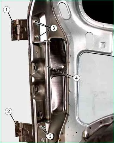
Assemble the upper 1 (Fig. 1) and lower 2 hinges together with the 4 hinge connector on the left pillar of the tailgate opening and secure without tightening with bolts 3.
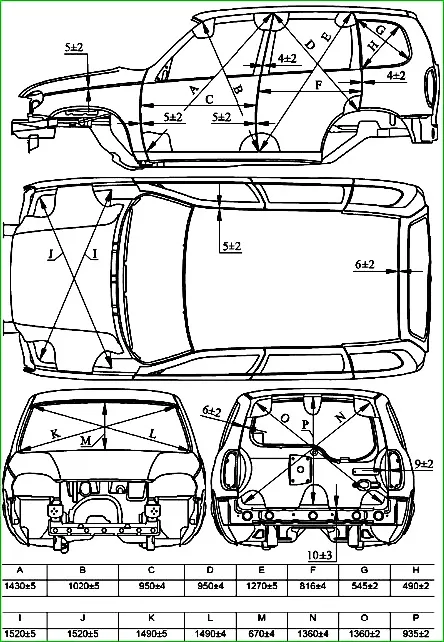
Install the tailgate assembly on the body in place and adjust it using technological wedges according to the gaps and protrusion/retraction in accordance with Fig. 2.
Perform the operation with an assistant.
Adjust the movable (welded) hinge links to the plane of the door end in place through the rear light niche and tighten bolts 3.
Punch the center of the holes in the movable links of both hinges on the end of the door to mark the points for drilling the holes and mark the position of the movable links with a scriber.
Drill two holes with a diameter of 8.2 mm in the end of the door according to the markings with a punch.
Fasten the movable hinge links to the door with M8 bolts, nuts and washers.
Carefully, supporting from below, hang the door on the body, secure the connector and check the tailgate for ease of opening/closing (make sure the hinge axes are aligned).
Disconnect the connector 3, and remove the door with hinges from the body, without disturbing the position of the movable links on the door pillar.
Install connector 3 on the door.
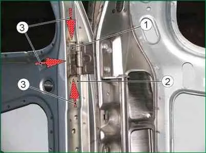
Make sure that the movable links are in the correct position on the end of the door (according to the marks made with a scriber) and weld the movable links of the hinges to the end of the door with a continuous weld with a leg of 3-3.5 mm, as shown in Fig. 4.
Clean up the welds and prepare the repaired section of the door for painting.
Install the door on the body with final adjustment of the opening, protrusion/retraction and adjust the door for ease of opening/closing.
Paint the door and hinges and install the removed units and parts.
Welding the side door hinges
Remove the units and parts from the car that interfere with straightening, welding and painting work on the body
Remove the door from the body.
Using a cutting machine, remove the remains of the damaged link 1 of the hinge and clean the welded place of the new hinge on the pillar 2 of the body to the metal.
Install the side door with the hinges in place on the body and, holding it in the closed position, adjust according to the opening and gaps, in accordance with Fig. 2, using technological wedges. Perform the operation with an assistant.
Pressing the fixed link 1 of the hinge to the rack 2 (with the door 3 closed), grab the hinge to the rack at three points along the perimeter of the hinge. Perform the operation with an assistant.
Carefully, supporting the door from below, check the door for ease of opening/closing (make sure that the hinge axes are aligned and that the door gaps with the mating parts comply with the requirements of Fig. 2). Perform the operation with an assistant.
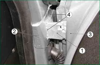
Remove the door and weld the fixed hinge link along the perimeter to the body pillar with a continuous weld 4 with a leg of 3-3.5 mm, as shown in Fig. 4.
Clean up the welds and prepare the repaired area of the body for painting and anti-corrosion treatment.
Install the door on the body with final adjustment of the opening, protrusion/retraction and adjust the door for ease of opening and closing.
Paint the damaged areas of the paintwork of the door and pillar and carry out anti-corrosion treatment of the weld of the fixed link of the hinge and hidden cavities of the pillar.
Install the removed units and parts of the car.
Welding the studs for fastening the threshold trim
Degrease the threshold of the side of the right or left body with white spirit or another degreasing agent available at the plant.
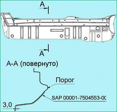
Prepare and apply the SAP 00001-7504553-00-00 device (Fig. 5) to the body threshold according to the instructions for use and align it with the lower flanging as shown in Fig. 4.
Attach the device to the body with adhesive tape, ensuring a tight fit to the body surface.
Attention: it is not allowed to use the device with defects that affect the accuracy of the marking.
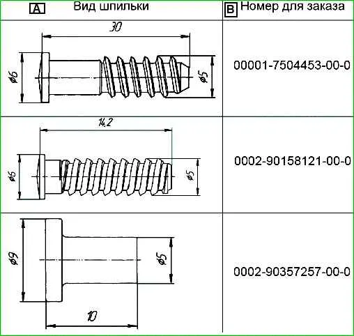
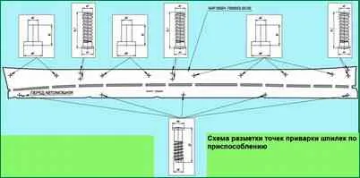
Weld the studs (Table 1) perpendicular to the plane of the threshold according to the marking with three welding points approximately 120 degrees around the circumference of the support area of the studs according to the diagram, Fig. 6.
Base points of body geometric dimensions
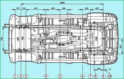
Basic transmission unit attachment points
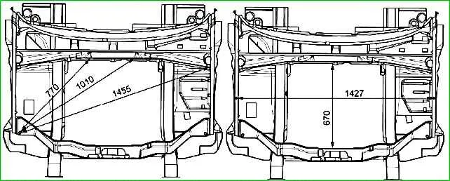
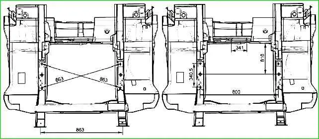
Front part of the body
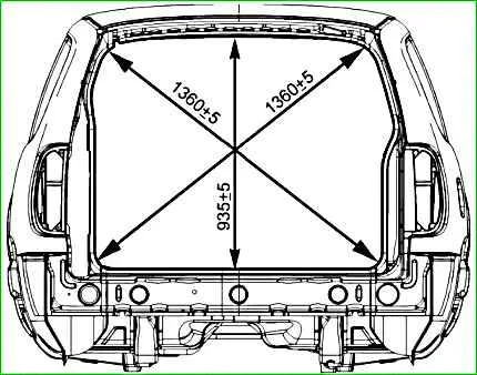
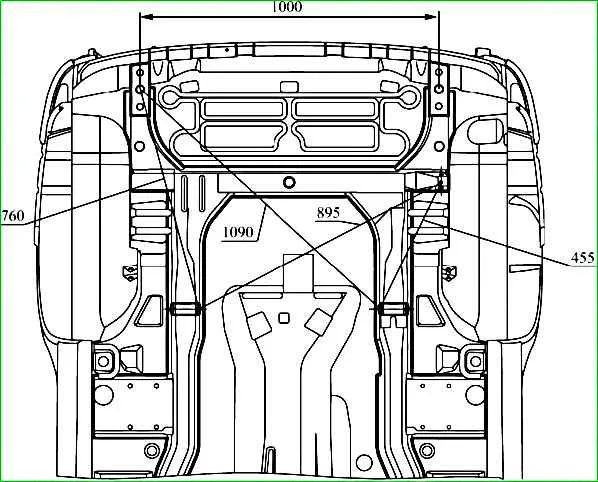
Rear part of the body
Galvanized metal
For parts operating in a corrosive environment (the lower part of the car), the manufacturer uses one- or two-sided galvanized metal.
The share of galvanized parts on the Chevrolet-Niva car body is more than 50 percent (by weight).
The following parts are galvanized on the Chevrolet-Niva body:
- 2123 – 5101024/025 front right/left floor panel;
- 2123 – 5101034 middle floor panel;
- 2123 – 5101042 floor panel rear;
- 2123 – 5101056/057 right/left floor sill connector;
- 2123 – 5101068/069 right/left floor sill box connector;
- 2123 – 5401092/093 right/left inner side panel;
- 2123 – 5401102/103 right/left lower side panel trim;
- 2123 – 8403024/025 right/left rear front fender reinforcement;
- 2123 – 8403264/265 right/left front fender splash guard;
- 2123 – 8404046/047 rear fender extension right/left;
- 2123 – 5401060/061 body side right/left;
- 2123 – 6101014/015 front door panel outer right/left;
- 2123 – 6101024/025 front door panel inner right/left;
- 2123 – 6201014/015 rear door panel outer right/left;
- 2123 – 6201024/025 rear door panel inner right/left;
- 2123 – 6301014 rear door panel outer;
- 2123 – 6301024 rear door panel inner;
- 2123 – 8403014/015 front wing right/left;
- 2123 – 8404014/015 rear right/left wing.
Galvanized sheets require different repair methods than regular steel panels:
When welding galvanized panels in a protective gas environment, the welding spot is more porous than when welding regular steel panels. Increase the number of welding spots by 10%.
Zinc releases harmful gas when burned in the welding zone. Use personal protective equipment.
Before applying putty to galvanized steel panels, carefully sand the smooth galvanized surface (remove shine) to increase the adhesion of the putty to the galvanized metal.
When working with galvanized steel panels, use only epoxy-based body putty.
Straightening a damaged body
During operation, some cars are damaged as a result of road accidents, which disrupts the integrity and geometry of the front surfaces, frame and base of the body.
When repairing such cars, it is necessary to restore the geometry of the attachment points of units and assemblies on the base of the body.
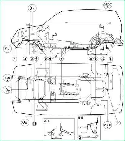
The main reference dimensions for checking the body base are shown in the figure.
Body damage can vary greatly in complexity. Therefore, the repair rules in each individual case should be the most appropriate for these damages, while it is necessary to use the possibilities of straightening damaged panels to the maximum.
If possible, it is necessary to avoid replacing welded parts, so as not to violate the factory complex of anti-corrosion protection of the body.
When performing body repairs, it is recommended to remove units and parts that interfere with straightening, welding and painting work in order to facilitate the measurement, control and installation of hydraulic and screw jacks to eliminate distortions and damage to the body.
Protrusion of front surfaces and removable parts relative to adjacent panels is eliminated by their fitting and adjustment.
Repair of deformed surfaces of parts
Repair of damaged body parts is carried out by drawing, straightening, straightening with metal shrinkage, cutting out areas that cannot be repaired, making repair inserts from rejected body parts or sheet metal with giving them shape of the part being restored.
Deformed areas of panels are usually straightened manually using special tools (hammers, levers, various mandrels) and devices.
Heat straightening is used to shrink (pull together) highly stretched panel surfaces.
To prevent deterioration of the mechanical properties of the metal, the panels are heated to 600–650° C (cherry-red color). The diameter of the heated spot should be no more than 10–15 mm.
Put the panels with metal shrinkage in the following order:
- – heat the metal points from the periphery to the center of the defective area with a carbon electrode of a semiautomatic welding machine or a gas torch and, using a wooden mallet or hammer, push down the heated spots from the back of the area being pushed down, using a support or anvil;
- – repeat the operations of heating and pushing down the metal until the required panel surface is obtained.
Irregularities on the panels can be leveled using polyester putties, thermoplastic, cold-curing epoxy mastics and solder.
Polyester putties such as "Khempropol-P" or PE-0085 form reliable connections with panels cleaned to metal.
The temperature in the work area should not be lower than 18° C. The prepared polyester putty should be used in no more than 10 minutes.
It finally hardens 60 minutes after application.
The thickness of the putty layer on the treated surface of the panel should not exceed 2 mm.
The thermoplastic is available in powder form.
It acquires the elastic properties necessary for applying it to the metal surface of the panel at a temperature of 150–160° C.
The surface to be filled must be thoroughly cleaned from rust, scale, old paint and other contaminants.
Thermoplastic adhesion is better to a rough metal surface.
To apply thermoplastic, the area to be leveled is heated to 170–180° C and the first layer of powder is applied, which is rolled with a metal roller.
Then the second layer is applied and so on until the unevenness is filled.
Each layer is rolled until a monolithic layer of plastic mass is obtained. After curing, the thermoplastic is processed with a straightening saw.
Solders such as POSSu 18-2 or POSSu 25-2 are used to level areas previously filled with solder, build up the edges of parts and eliminate gaps.
If body parts are significantly damaged, they are replaced with new ones using electric arc welding in a protective gas environment.


