In this article we will look at how to replace the sensors of the VAZ-2123 engine management system
Removing and installing the crankshaft position sensor
The sensor is installed on the timing cover, in its lower part
You will need a screwdriver.
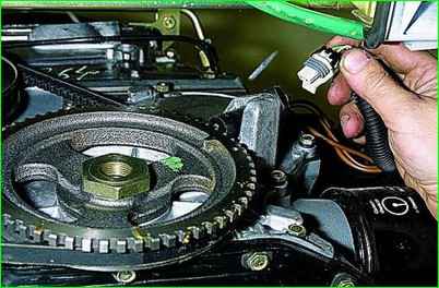
Using a screwdriver or your finger, press down the plastic latch securing the wiring harness connector and disconnect the connector from sensor.
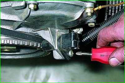
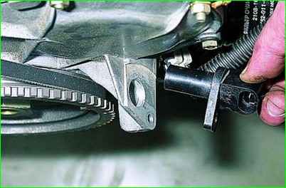
Turn off the sensor mounting screw and remove the sensor from the cover lug hole
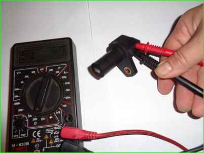
Check sensor resistance. A working sensor should have a resistance of 0.55–0.75 kOhm.
Install the sensor in the reverse order of removal.
Removing and installing the coolant temperature sensor
The sensor is screwed into the hole in the front water jacket pipe of the cylinder head.
You will need a 19 mm wrench.
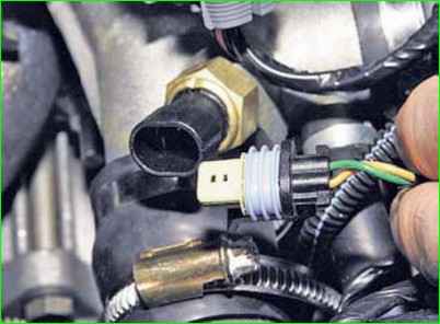
Use a screwdriver or your finger to pry up the plastic latch securing the wiring harness connector and disconnect the connector from the sensor.
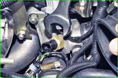
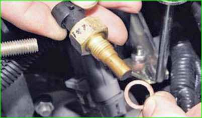
Loosen tighten the sensor and unscrew it from the pipe hole together with the sealing ring
Check the resistance of the sensor. At 20°C, a serviceable sensor should have a resistance of 2.2–2.4 kOhm.
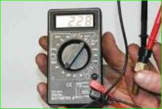
The resistance of the sensor changes depending on the temperature over a wide range.
At high temperatures, the resistance of the sensor is low (70 Ohm at 130 °C), and at low temperatures, it is high (100.7 kOhm at –40 °C).
Install the sensor in the reverse order of removal.
Removing and installing the throttle position sensor throttle position sensor
The sensor is mounted on the throttle assembly and connected to the throttle shaft.
You will need a screwdriver.
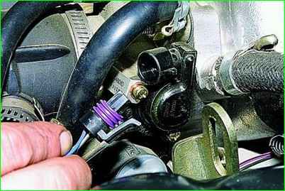
Disconnect the wiring harness connector from the sensor.
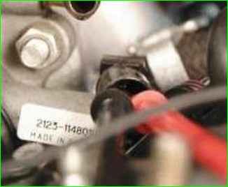
To check the sensor, measure the resistance between terminals "2" and "3" of the sensor connector.
Move the throttle valve from the fully closed position to the fully open position.
The resistance of a serviceable sensor should vary uniformly within 2.7–8.2 kOhm.
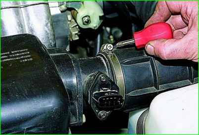
Loosen the clamp securing the left side of the air intake pipe to the sensor and disconnect it from the sensor.
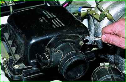
Unscrew the two bolts securing the sensor to the air filter cover and remove the sensor together with the sealing ring
Install the sensor in the reverse order of removal.
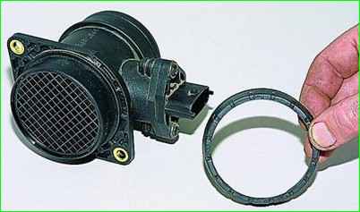
If the new sensor does not have a rubber sealing ring, transfer the ring from the removed sensor to it.
Removing and installing the knock sensor
The knock sensor is installed on the right side of the engine block in its upper part, near the second and third cylinders.
You will need: a 13 mm wrench, a screwdriver.

To make it easier to access the sensor, remove the lower mounting bolt of the front intake manifold strut and move the strut aside.
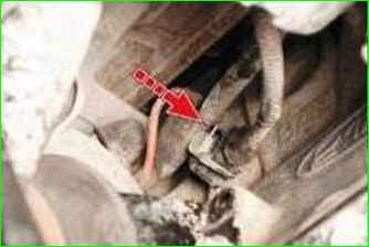
Press the spring clip of the wiring harness connector and disconnect the connector from the sensor.
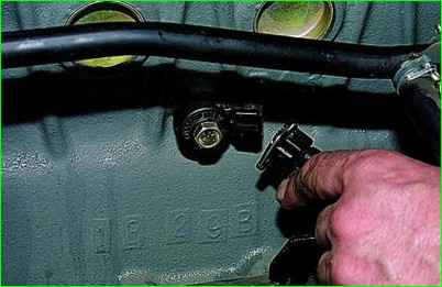
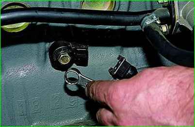
Unscrew the bolt securing the sensor to the cylinder block and remove the sensor.
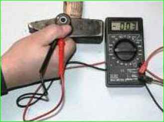
Connect the autotester connected in voltage measurement mode to the sensor terminals.
Tap the sensor body on a hard massive object (for example, a hammer).
The voltage should change.
If the voltage remains constant, the sensor is faulty and must be replaced.
The sensor can be checked more accurately with the engine running using the DST-2 diagnostic tool.
Install the sensor in the reverse order of removal.
Removing and installing the oxygen sensor
The sensor is installed on the exhaust pipe of the exhaust system. gases.
You will need a 22 mm wrench.
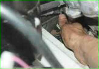
Press the spring clip to disconnect the sensor and engine harness connectors.
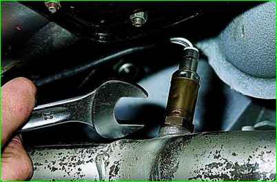
Loosen the sensor and remove the sensor from the exhaust pipe
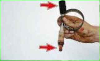
Install the sensor in the reverse order of removal
Make sure that no grease or dirt gets on the sensor tip and the wiring harness connector.
Tighten the sensor to a torque of 40–45 Nm
Removing and installing the speed sensor
The sensor is installed on the rear cover of the transfer case, so it is more convenient to work on a lift or inspection pit.
You will need a 22 mm wrench.
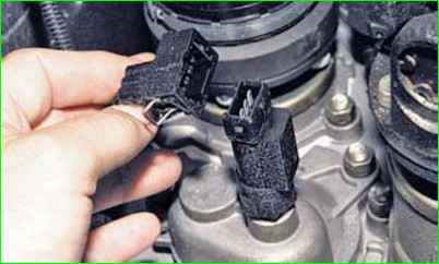
Press the spring clip to disconnect the wiring harness connector from the sensor
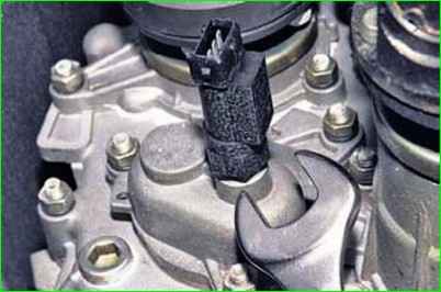
Loosen the sensor and unscrew it from the drive.
Install the sensor in the reverse order of removal.
Removing the camshaft sensor (phase sensor)
If the sensor is faulty, the malfunction lamp in the instrument cluster lights up.
If the engine is not running for a long time, it is difficult to start.
Also Weak engine responsiveness and increased fuel consumption.
The sensor is installed in the front part of the cylinder head.
To remove the sensor, disconnect the negative terminal of the battery
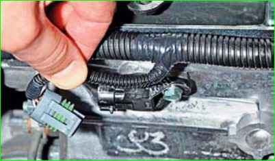
Press the retainer and disconnect the block from the phase sensor
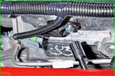
Using a 10 mm socket, unscrew the bolt securing the sensor to the cylinder head
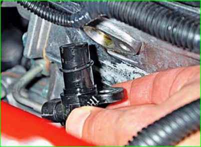
Remove the sensor from the hole in the cylinder head
The sensor connection is sealed with a rubber ring (usually when purchasing new sensor, it comes without this ring)
If the ring has lost its elasticity, it needs to be replaced
Install the sensor in the reverse order
Tightening torque of the sensor mounting bolt is 6-8 Nm.


