You will need: a 13 mm wrench, a 19 mm wrench (two), a punch, and a hammer
Unscrew the four self-locking nuts securing the constant velocity joint (CV joint) to the flange of the transfer case input shaft
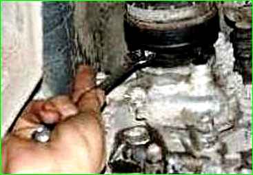
Reusing self-locking nuts is not allowed, replace them with new ones
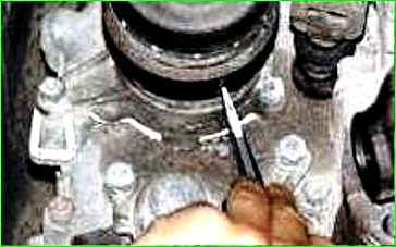
Using a hammer and chisel, carefully mark the relative positions of the CV joint housing and the transfer case flange.
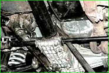
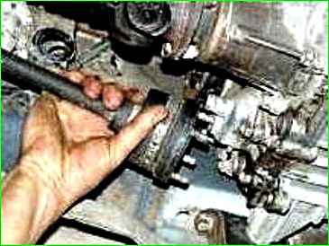
Loosen the nuts securing the power unit mounts, use a crowbar to move it forward 1.5–2.0 cm and remove the hinge pins from the flange holes.
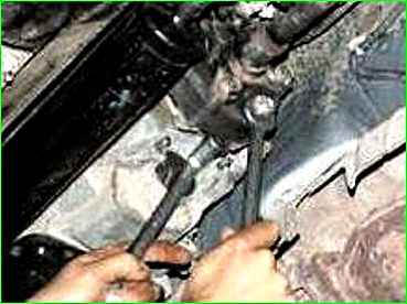
Unscrew the three nuts of the bolts securing the flexible coupling to the flange of the secondary shaft of the gearbox.
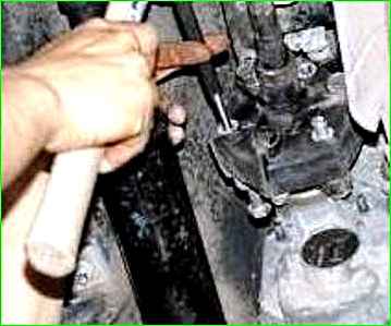
Remove the bolts from the holes in the coupling and flange.
If the bolts are difficult to remove, use a punch and hammer.
Remove the shaft.
Install the intermediate shaft in the reverse order of removal.
Disassembling and assembling the intermediate shaft shaft
You will need: a 13 mm wrench, a 19 mm wrench (two), a screwdriver, sliding pliers, and a hammer.
Thoroughly clean the constant velocity joint with a wire brush.
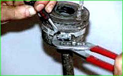
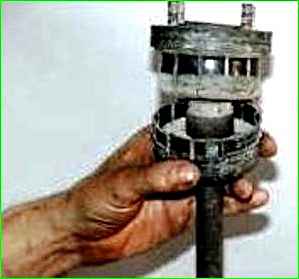
Remove the clamp securing the joint boot casing using a screwdriver and sliding pliers and slide the casing along the shaft to gain access to the boot.
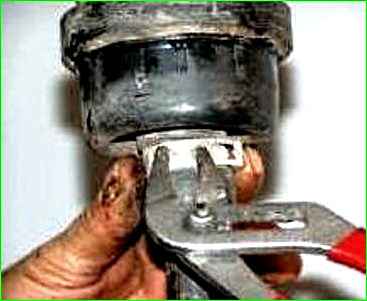
Remove the clamp securing the boot using sliding pliers.
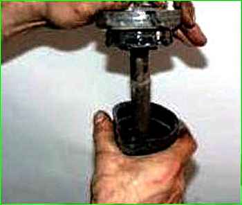
Slide the joint boot along the shaft and mark the relative position of the joint and shaft in any convenient way
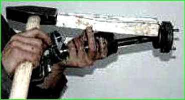
Using a hammer and a wooden spacer, knock off and remove the joint from the shaft.
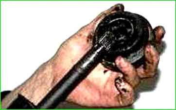
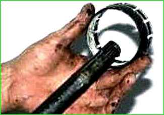
Remove the boot and the joint boot casing.
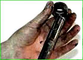
Remove the joint boot valve.
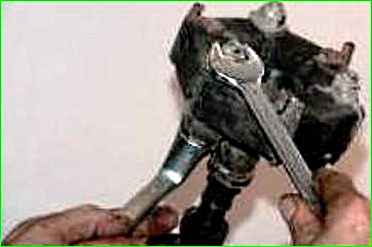
Unscrew the three nuts of the flexible coupling bolts.
Mark the relative position and number of balancing washers before removing them from the coupling.
Remove the bolts and remove the coupling.
Install the removed parts on the shaft in the reverse order of removal, aligning the marks applied before disassembly.


