For safety reasons, the first time you turn on the ignition on the car, you should do the following:
- - connect the negative terminal of the wire to the battery;
- - open the driver's door;
- - without sitting on the seat, turn on the ignition with your right hand, placing it under the steering wheel, while the head of the specialist performing this operation should not be between the steering wheel and the driver's seat.
After turning on the ignition, if there are no faults, the diagnostic indicator (yellow "SRS" inscription) should turn on for 6-7 seconds and turn off
Turn off the ignition. In case of removal/installation of the steering wheel, press the switch to make sure that there is a sound signal.
Forced activation of the MNPBV, MNPBP, seat belt pretensioner
Only the deployed airbag module and seat belt pretensioner are subject to disposal.
The non-deployed airbag module and pretensioner intended for disposal must be forcibly deployed (forced to start) in a manner that does not harm the ecology and the environment (i.e. burning, dissolving, etc. is prohibited).
The activation of modules and pretensioners is carried out by an organization that has the appropriate right and license to carry out work with pyrotechnic products. To activate the module or pre-tensioning devices:
- - connect the original block of a two-channel wire at least 15 m long to the connector of the gas generator igniter (pre-ensure the closure of the free contacts of the wire);
- - place the airbag module or pre-tensioning device in a tank with a capacity of at least 200 l (the metal tank must have at least 10 holes with a diameter of about 50 mm in the top cover to release gas and relieve pressure created during the activation of the system components; the cover must be fixed);
- - ensure that people are removed to a safe distance from the place of activation;
- - the person performing the activation must be protected by a shelter (solid fence, wall, etc.);
- - open the free contacts of the two-channel wire connected to the igniter the gas generator igniter, and apply a constant voltage of 12 V to them (it is allowed to be from a car battery), thereby performing a forced start.
Only one unit of the module or the seat belt pre-tensioner can be forced to start.
After the module has been triggered, its surface temperature reaches 100° C, so it is necessary to wait about 30 minutes for the module surface to cool, remove the module from the tank and dispose of it.
Before disposal, it is necessary to disassemble the module into its component parts by unscrewing the fasteners and separating the component parts.
Dispose of the component parts in accordance with the type of module materials, in compliance with current environmental and environmental protection requirements.
The seat belt pre-tensioner has a non-separable design and is disposed of in accordance with the type of material and in compliance with current environmental and environmental protection requirements. environment.
Diagnostics of the airbag system

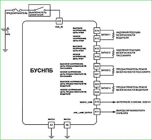
The electrical connection diagram of the Chevrolet Niva airbag control unit is shown in Fig. 1.

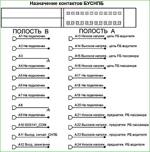
The assignment of contacts of the airbag control unit is shown in Fig. 2.

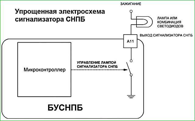
A simplified electrical circuit of the diagnostic indicator is shown in Fig. 3.
To view the fault codes and parameters of the SNPB, use the diagnostic device DST-2, 10,12 with the appropriate firmware, connected to the vehicle's diagnostic socket.
The list of fault codes displayed by the diagnostic device in the "Faults" mode is given in Table 2.
If a fault of the "High resistance" type is detected, the leniye of contacts…» check:
- - reliability of connection of the instrument panel harness connector to the BUSNPB;
- - reliability of connection of the connector to the corresponding component of the SNPBV (MNPBV and rotating device, MNPBP, seat belt pretensioner);
- - the corresponding electrical circuit to the BUSNPB for an open circuit (before checking the circuit, be sure to disconnect the connectors from the BUSNPB and the corresponding component of the SNPB).
If the air bag system is in good working order, the indicator lights up when the ignition is turned on or after starting the engine and then goes out after 6-7 seconds.
Attention! If the ignition is turned on again in an interval of less than 15 seconds after the ignition is turned off, the SRS indicator will not turn on.
It is recommended to maintain an interval of at least 15 seconds before turning the ignition on again. This condition does not indicate a malfunction.
A system malfunction is indicated by flashing, constant illumination or absence of the indicator.
Table 1 - Information system
Behavior of the SRS indicator when the ignition is turned on - Meaning
It turns on and then goes out after 6 sec. - System is OK
Comes on and does not go out - Faulty airbag module, airbag control unit, airbag wiring or airbag connector
Comes on, goes out after 6 sec, comes on again and does not go out - Faulty airbag module, airbag control unit, airbag wiring or airbag connector
Does not come on - Faulty SRS fuse, airbag warning lamp in instrument cluster, airbag module, airbag control unit or airbag connector
If condition «1» is incorrect, connect the diagnostic tool and determine the fault code.
If the control unit is in the locked state, as evidenced by the constant lighting of the indicator after the ignition is turned on, it must be unlocked using the diagnostic tool, for which in the airbag menu select:
«Additional tests» «Unlocking airbag» «Airbag unlocked".
If the forced shutdown (blocking) function of the NBP module in the NBP system is activated, then after the ignition is turned on, the diagnostic indicator will be constantly lit.
Table – 2 List of fault codes
- B1015 - Open circuit of the passenger airbag igniter
- B1016 - The passenger airbag igniter circuit is shorted to each other
- B1018 - The passenger airbag igniter circuit is shorted to ground
- B1019 - The passenger airbag igniter circuit is shorted to +12
- B1021 - Open circuit of the driver airbag igniter
- B1022 - The driver airbag igniter circuit is shorted to each other
- B1024 - Pyrotechnical igniter circuit Driver seat belt pretensioner shorted to ground
- B1025 - Driver seat belt pretensioner igniter circuit shorted to +12
- B1031 - High supply voltage
- B1032 - Low supply voltage
- B1041 - Driver seat belt pretensioner igniter circuit open
- B1042 - Driver seat belt pretensioner igniter circuit shorted to each other
- B1043 - Driver seat belt pretensioner igniter circuit shorted to ground
- B1044 - Driver seat belt pretensioner igniter circuit shorted to +12
- B1045 - Passenger seat belt pretensioner igniter circuit open
- B1046 - Passenger seat belt pretensioner igniter circuit shorted between by itself
- B1047 - Passenger seat belt tensioner igniter circuit shorted to ground
- B1048 - Passenger seat belt tensioner igniter circuit shorted to +12
- B1051 - ACU unlocked
- B1052 - ACU low ignition energy
- B1053 - Impact data overflow
- B1061 - AWL lamp shorted to ground
- B1062 - AWL lamp shorted to +12
- B1071 - ACU internal error
Table – 3 Displayed variables
Parameter - Name
- Spr PB vod - Resistance Driver Airbag Igniter Ohm
- Spr PB Pass - Passenger Airbag Igniter Resistance Ohm
- Spr RB Vod - Driver Airbag Pretensioner Igniter Resistance Ohm
- Spr RB Vod - Passenger Airbag Pretensioner Igniter Resistance Ohm
- Nap Ignition - Measured ACU Ignition Voltage V
- Block SNPB - SNPB Lock Status


