Prepare the car and disconnect the negative terminal of the battery
The airbag control unit circuit has an emergency power reserve
In order to discharge the capacitors after turning off the ignition, you must wait at least 10 seconds before performing work
Removing the driver's airbag module
Set the front wheels to the position of straight-line movement of the car. The upper spokes of the steering wheel should be horizontal.
Open the left front door.
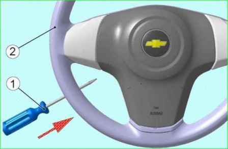
Standing outside the car, to the side of the steering wheel, insert a flat-blade screwdriver 1 (Fig. 1) into the left hole on the steering wheel, press on the screwdriver, and release the module from the steering wheel retainer.
Turn the steering wheel 180 degrees and insert the flat-blade screwdriver into the right hole on the steering wheel.
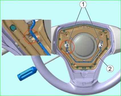
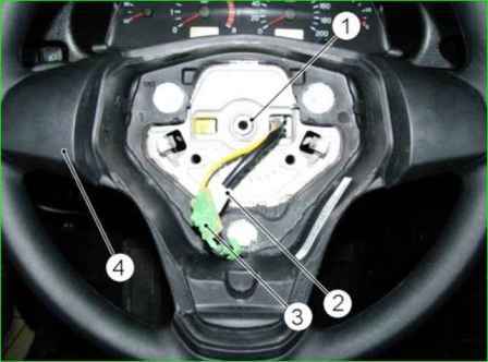
Press the screwdriver to release the module from the locks 1 (Fig. 2) of the steering wheel.
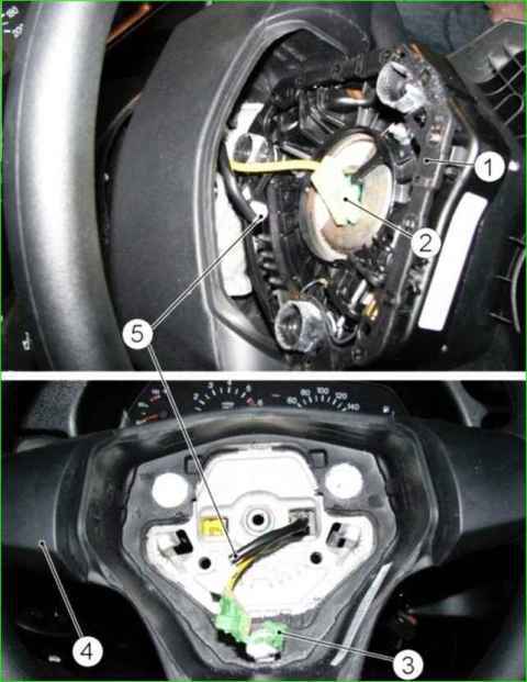
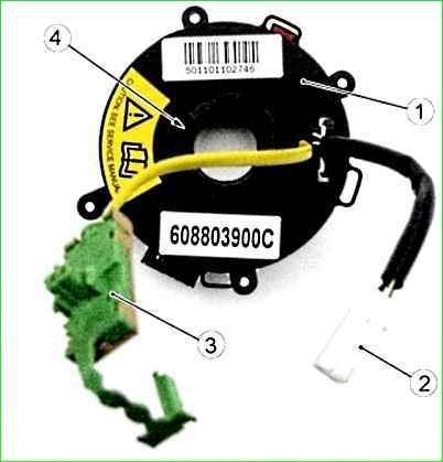
Return the steering wheel to its original position, remove module 1 (Fig. 3) of the airbag without putting tension on the harness of the L-shaped connector.
Using a flat-head screwdriver, disconnect the retainer 3 and disconnect the L-shaped connector 2 from the module, disconnect connector 5 of the horn, remove module 1 of the gas generator.
Attention. Place the non-detonated gas generator module on a flat surface with the facing cover facing up.
If the L-shaped block melts when dismantling the detonated gas generator module, disconnect the module by cutting the block harness.
Installing the driver's airbag
Before installing the gas generator module, visually check for mechanical damage and for the presence of a label with a barcode and identification number on the gas generator module.
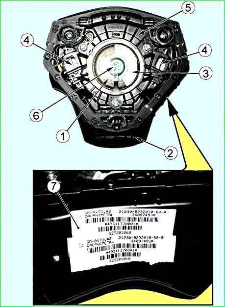
Attention. When installing a new gas generator module, tear off label 7 (Fig. 4) with a barcode from the gas generator module and paste it into the "Special Notes" section of the service book, indicating the installation date and vehicle mileage, and the reason for replacement.
Standing outside the vehicle to the side of the steering wheel, bring the gas generator module to the installation location in the steering wheel, connect the horn pads, and without applying lateral force, insert the L-shaped pad into the gas generator module connector until you hear a characteristic locking click.
Insert the retainer into the pad until you hear a characteristic click.
Attention. Before installing the retainer in the L-shaped block, the airbag module is in the transport position, the contacts of the igniter connector are bypassed.
Bring the gas generator module to the steering wheel socket, then insert the airbag module into the steering wheel until it clicks.
Removing the connector with a rotating device
Remove the driver's airbag as described above
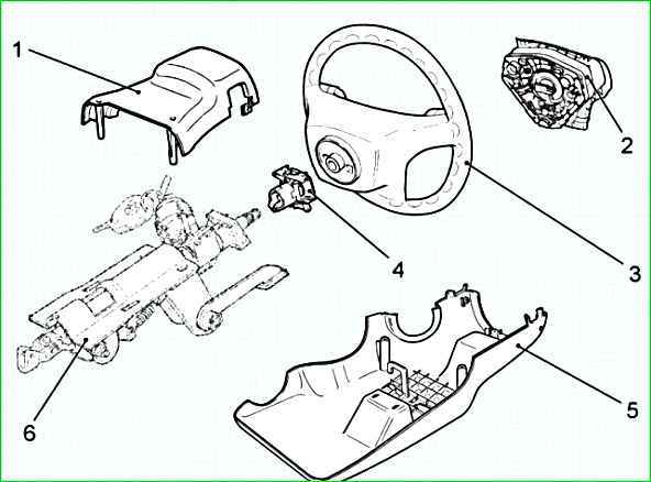
Unscrew the fastening screws and remove the upper trim casing 1 (Fig. 5) and the lower trim casing 5.
Remove the sealing ring from the ignition switch.
Set the front wheels to the straight-ahead position. The upper spokes of the steering wheel should be horizontal.
Unscrew nut 1 (Fig. 6) of the steering wheel fastening and remove the steering wheel 4 from the steering shaft, passing connectors 2 and 3 of the wire harness through the hole in the steering wheel hub.
Attention. After removing the steering wheel, exclude axial movement of the cylindrical retainer.
To avoid breakage, do not rotate the cover of the rotating device, as it is automatically fixed.
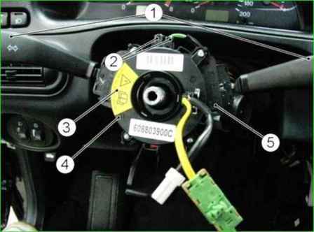
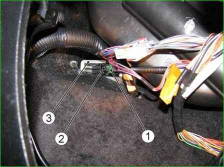
Remove switches 1 (Fig. 7) of windshield wipers and light signaling from the connector.
Disconnect pads 2 of the instrument panel harness from the connector.
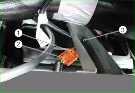
Loosen bolt 3 (Fig. 8) and remove the connector with the rotating device from the steering shaft as a whole.
Installing the connector with the rotating device
Attention. The connector with the rotating device must be installed on the steering shaft immediately before installing the steering wheel on the shaft.
Before installation, the steering arm must be in the middle position, while the front wheels must be in the position of straight-ahead movement of the car.
Install connector 1 (Fig. 8) with the rotating device on the steering shaft, do not tighten bolt 3 of the connector mounting.
Attention. If the cover of the rotating device rotates unintentionally, it must be set to the middle position.
To do this, press the cylindrical retainer 4 (Fig. 9) and, carefully rotating it left or right until you feel a noticeable resistance, bring the cover 1 of the rotating device to the extreme position.
After that, turn the cover 1 two full turns in the opposite direction and on the third turn, set it in the position shown in Figure 7 (label 3 should be on the left, the leads of the wire harnesses on the right).
Release the cylindrical retainer, while the cover should be fixed in a fixed position.
When installing a new connector with a rotating device, remove the red transport lock from the rotating device that locks the movable element of the device in the middle position, rotate the transport lock around its axis by 150°+30°.
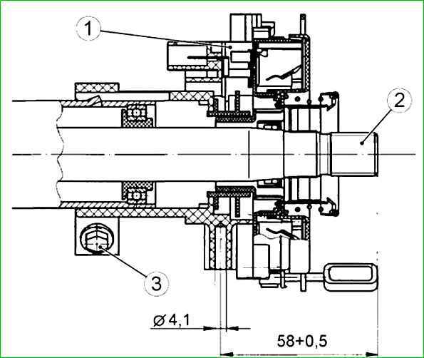
Move connector 1 (Fig. 10) with the rotating device assembly along the shaft axis so that the control dimension from the end of shaft 2 to the axis of the screw securing the lower trim casing to the connector is 58+0.5 mm. Screw in and tighten bolt 3.
Connect the instrument panel harness pads to the connector.
Attention. Before installing the steering wheel on the steering shaft, make sure that the front wheels of the vehicle are in the direction of rectilinear motion.
Put pads 2 and 3 (Fig. 11) of the rotating device into the right hole of the steering wheel hub and install the steering wheel 4 on the steering shaft. In this case, the upper spokes of the steering wheel should be in a horizontal position.
Tighten and tighten nut 1 of the steering wheel fastening observing a tightening torque of 31.4 ... 51 Nm (3.2 ... 5.2 kgf.m).
Install the windshield wiper and light signaling switches in the connector.
Install the sealing ring on the ignition switch.
Install the upper and lower trim covers and secure them with screws.
Turn the steering wheel to the right and left until it stops, make sure there are no jams, knocks, and that the rotation is smooth, as well as the functionality of the lever release turn signals.
By shaking the steering wheel, make sure there is no radial and axial play in the steering wheel.
Install the driver's airbag module
Removing the airbag control unit
Remove the instrument panel as described in the article - Removing the instrument panel of a Chevrolet Niva manufactured since 2009
Move lock 1 (Fig. 12) of the pad to the side and disconnect pad 2 of instrument panel wiring harness from the connector of airbag control unit 3.
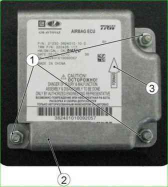
Unscrew nuts 1 (Fig. 13) securing unit 2 of the SNPB control system and remove the control unit.
Installing the SNPB control unit
Install the control unit in the reverse order of removal.
When installing the SNPB control unit, arrow 3 on the unit cover must point in the direction of vehicle travel.
Attention. The SNPB control unit is supplied as spare parts in a locked state. After replacing the control unit, it must be unlocked.
Removing the passenger airbag module
Remove the instrument panel storage compartment.
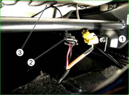
Disconnect connector 1 (Fig. 14) of the additional wiring harness from connector 2 of the instrument panel wiring harness. Disconnect bracket 3.
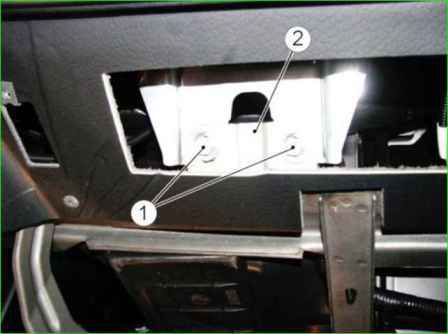
Unscrew bolts 1 (Fig. 15) securing the module to bracket 2 of the instrument panel cross member.
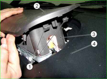
Through the opening of the glove compartment, alternately acting on the locks 1 (Fig. 16) of the trim cover 2 of the MNPBP, feeding from below, remove the module 3 of the NPBP from the instrument panel 4.
Attention. Place the unactivated NPBP module on a flat surface with the trim cover facing up.
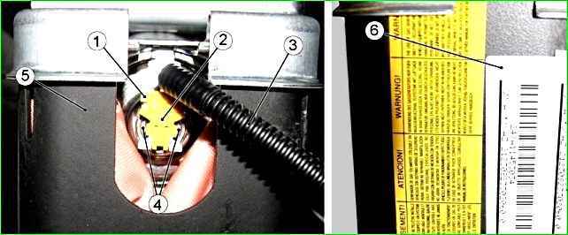
Using a flat-blade screwdriver, remove retainer 2 from the L-shaped connector 1 (Fig. 17) connected to the MNPBP connector, then, using a thin flat-blade screwdriver, press the retaining tabs 4 of the connector and disconnect the L-shaped connector 1 from the module connector 5 and remove the additional wiring harness 3.
If the deployed NBP module is dismantled, check the serviceability of the wiring harness to the NBP module. If damage to the connector to the NBP module, melting, breakage or short circuit of the wires to the NBP module is detected, replace the harness.
Installing the passenger airbag module
Before installing the MNPBP, visually check for mechanical damage and the presence of a label with a barcode and identification number on the module.
Attention. When installing a new NBPPS module, tear off label 6 (Fig. 17) with a barcode from the module and paste it into the "Special Notes" section of the service book, indicating the installation date and vehicle mileage, and the reason for replacement.
Insert the L-shaped connector of the additional instrument panel wiring harness into the NBPPS module connector until you hear a characteristic locking click.
Insert the retainer into the L-shaped connector until you hear a characteristic click.
Attention. Before installing the retainer in the L-shaped block, the airbag module is in the transport position, the contacts of the igniter connector are bypassed
Install the airbag module in the instrument panel and fix the MNPBP cover in the instrument panel.
Tighten and tighten the bolts securing the MNPBP to the bracket observing the tightening torque of (8+1) Nm, while ensuring a uniform gap between the MNPBP cover and the instrument panel.
Connect the additional harness to the instrument panel harness, install the instrument panel storage compartment.
Removing the seat belt pretensioner
Press the seat movement mechanism lever and move the front seat back.
Disconnect connector 1 (Fig. 18) of wiring harness of front seat belt pretensioner.
Disconnect connector 2 of wiring harness of seat heating (if equipped).
Remove front seat
Caution. Always wear gloves when removing/installing the seat belt pretensioner.
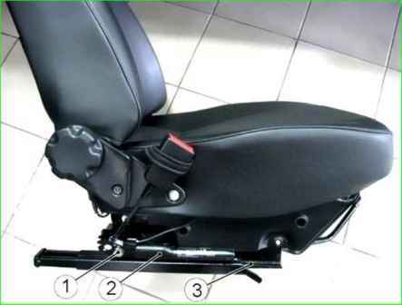
Unscrew bolt 1 (Fig. 19) securing the seat belt pretensioner and, carefully holding the pyrotechnic tube, disconnect the seat belt pretensioner 2 with the spacer from the front seat runners 3.
Installing the seat belt pretensioner
Before installing the seat belt pretensioner, visually check for mechanical damage.
Install the front seat belt pretensioner with the spacer on the front seat runners, tighten the pretensioner mounting bolt.
Install the seat in the vehicle interior in the reverse order of removal.
Connect the front seat belt pretensioner wiring harness connector to the rear wiring harness connector. Connect the seat heating harness connector (if equipped) to the rear harness connector
After completing the work on removing/installing the airbag components, connect the ground wire terminal to the battery.
Caution. When connecting the ground wire terminal to the battery, the ignition must be off. At the same time, no one must be in the vehicle.