Depending on the trim level, two types of fog lights are installed on the vehicle
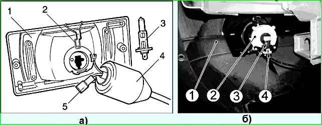
In fog lamp 1 (Fig. 1a) (GLS trim level), replace the burnt-out lamp 3 by first removing the lamp from the vehicle.
To remove the lamp, remove the protective rubber cover 4 and remove the spring latch antennae 2 from the grooves.
For ease of dismantling the lamp, first remove the connector 5 from it.
To replace the lamp in fog lamp 2 (Fig. 1b) (GLC trim level 55), disconnect connector 4 of the front wiring harness from the lamp and remove lamp 3 from the headlight housing.
More details:
Remove the front bumper mudguard for this:
Turn the front wheel or remove it.

Unscrew the two screws at the bottom of the bumper

Unscrew the four screws inside the wing arch

Use a 10 mm socket to unscrew the two nuts

Remove the mudguard.
After removing the mudguard, we proceed to replacing the fog lamp bulb

Press the two clamps of the wire block

Disconnect the socket from the lamp

Turn the lamp counterclockwise and remove it from the headlight housing
Install the new lamp in the reverse direction sequences
Removing the fog lamp housing

Use a Phillips screwdriver to unscrew the three screws securing the headlight to the bumper

Removing the headlight

Using a screwdriver, press the two connector clamps and disconnect the wiring connector from the headlight bulb.

If necessary, use a Torx 20 key to adjust the direction of the headlight beam through the hole in the bumper.
Install the fog light in the reverse direction sequence.
The right headlight is marked with the letter R, the left headlight with the letter L.
Adjusting the fog lights
The headlights are adjusted using optical instruments.
If there are none, then the adjustment can be carried out on a horizontal platform using a screen.
The unevenness of the working area should be no more than 3 mm per 1 meter.
Put a fully fueled and equipped car, with a load of 735 N (75 kgf) on the driver's seat, on a flat horizontal platform 10 m from the screen (a shield measuring about 2x1 m, etc.) so that the axis of the car is perpendicular to it.
Before marking the screen, make sure that the air pressure in the tires is 0.19 MPa (1.9 kgf / cm 2), and then squeeze the car suspension 2-3 times to adjust its components automatically.
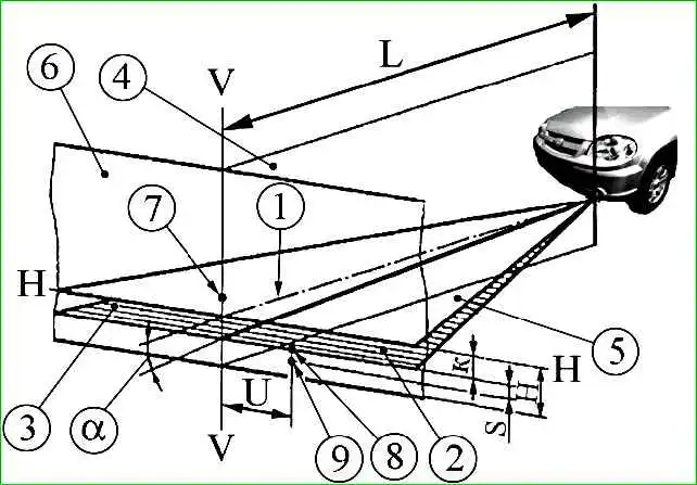
Check and, if necessary, adjust the direction of the fog lights.
In this case, the upper cut-off line of the fog light beam should be parallel to the plane of the working platform on which the vehicle is installed.
The headlights are adjusted by turning screw 1 (figure), which rotates the optical element in the horizontal plane.
The luminous intensity of the fog lights, measured in the vertical plane passing through the reference axis, should be no more than 625 cd in the direction 3º upward from the position of the cut-off line.
If the luminous intensity does not correspond to the value specified above, repeat the adjustment by no less than 0.5% in the vertical direction from the angle value of 69 and measure the luminous intensity.
")

")
")
")
")
")
")
")