The pump is removed for repair or replacement if it makes noise during operation that exceeds the normal level, and coolant leaks
Drain the coolant from the engine (described in the article - Replacing the coolant of the Niva Chevrolet)
Remove the auxiliary drive belt (described in the article - How to replace the alternator belt of the Niva Chevrolet)
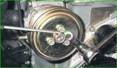
Use a 13 head to loosen the tightening three bolts securing the coolant pump pulley
Hold the pulley from turning with a flat-head screwdriver, alternately inserting it between the head of each mounting bolt and the flange of the pulley hub.
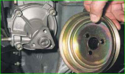
Unscrew the bolts and remove the pulley
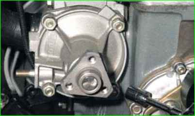
Using a 13 mm head, unscrew the four nuts securing the coolant pump cover
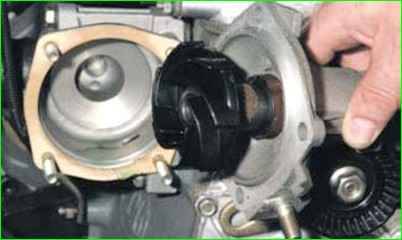
Remove the pump cover complete with impeller and bearing
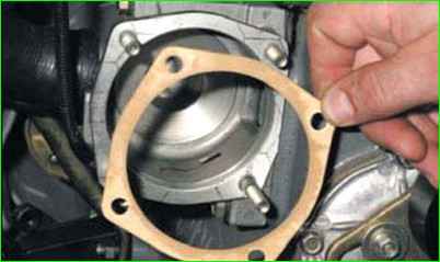
The joint of the cover and the pump body is sealed with a gasket
We install the pump cover in the reverse order
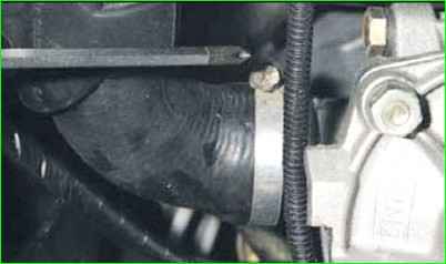
To remove the coolant pump assembly, use a screwdriver to loosen the clamp securing the inlet hose to the pump body
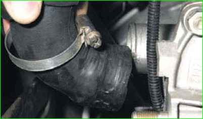
Remove the hose from the body branch pipe
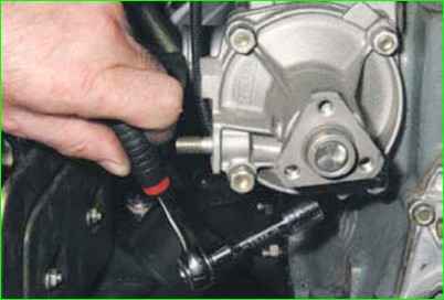
Using a 13 mm head with an extension, unscrew the two bolts of the lower mount of the pump housing to the cylinder block
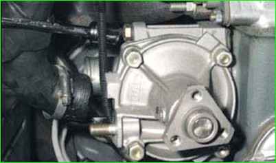
Unscrew one bolt of the upper mount
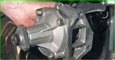
Removing the coolant pump assembly
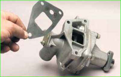
The joint of the coolant pump housing and the cylinder block is sealed with a gasket
We install the pump in the reverse order
Fitting the pump cover to the housing
The bearing and oil seal are installed in the pump cover with tension, in addition, the pulley hub and impeller are pressed onto the shaft.
In this regard, disassembling the pump is quite labor-intensive, so in case of a malfunction, we recommend replacing the cover assembly with all the included parts.
You can replace the pump together with the housing, but basically, if the housing is in normal condition, then only the shaft itself with the impeller is replaced.
In this case, you just need to correctly select and adjust the parts.
Let's consider the simplest old-fashioned method of selecting and replacing these parts.
Before installing a new cover (assembled), be sure to check the gap between the impeller blades and the pump housing.
It should be 0.9-1.3 mm. If it is too big, If the gap is too small, the pump flow will be reduced, and if it is too small, the impeller blades may touch the casing walls and break.
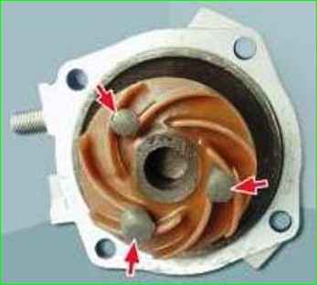
To check the gap between the impeller and the pump casing, make three "pillars" from plasticine and install them between the blades so that they protrude 2-3 mm above the blades.
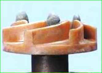
Install the gasket on the cover.
Install the cover to the housing by tightening the four nuts.
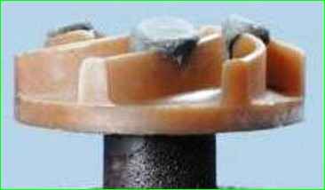
Remove the cover. The "columns" will be compressed.
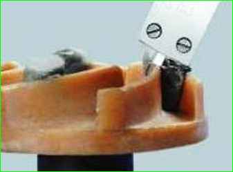
Use a caliper to determine the protrusion of the "columns" above the blades.
The protrusion value is equal to the gap between the blades and the pump housing.
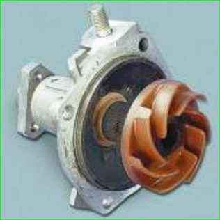
Remove the "posts" and install the cover and removed parts in the reverse order of removal.
Adjust the tension of the water pump and generator drive belt.
Fill with coolant and remove air locks from the cooling system.


