With the engine running and the vacuum booster in working order, the brake pedal when braking should not reach the floor of the cabin - the gap between the pedal and the floor should be at least 40 mm
The performance of the vacuum booster is checked as follows: with the engine not running, you must press the brake pedal 3-4 times, and then, when you press the pedal again, holding it with a force of 300-400 N (30-40 kgf), start the engine.
If the amplifier is working properly, the pedal will move slightly to the floor, and the hiss of air passing through the amplifier filter will be heard.
If the pedal does not move or is difficult to move, then the cause is a faulty amplifier or incorrect engine idle adjustment.
You also need to make sure that the vacuum booster and check valve are tight.
To do this, turn off the engine, wait for 1-2 minutes and press the pedal several times.
During the first three presses, you should hear the sound of air entering the amplifier.
If this does not happen, the vacuum booster or check valve is faulty.
The amplifier should only be completely disassembled when necessary.
Remove the amplifier from the car and disassemble it in the following order:
- - clean the amplifier from dust and dirt, disconnect the rubber hose from the check valve, and the main cylinder from the amplifier;
- - secure the master cylinder with the reservoir so that liquid does not spill out of it (this eliminates bleeding of the system after repair);
- - remove the cotter pin, unscrew the nut securing the pusher eye axle to the brake pedal and remove the spring washer, axle and plastic bushings;
- - unscrew the four nuts securing the vacuum booster to the front panel of the cab, remove the booster from the engine compartment;
Details of removing and installing the vacuum booster can be found in the article - “How to replace the vacuum brake booster of a Gazelle car”
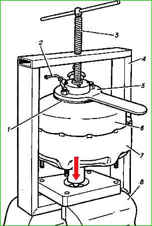
- - fasten with two nuts on the studs of the cover 6 (Fig. 1) of the housing a special plug 5 with a handle for turning the cover and with a tube 2 for connecting a vacuum gauge;
- - install the vacuum booster in a special device 4, secured in a vice 8;
- - screwing screw 3 into the device, recess the cover 6 of the vacuum amplifier until a small gap appears in the connection between the cover and the housing 7;
- - insert the extension into the handle of the plug and turn the handle until the protrusions on the body coincide with the slots on the cover. Unscrew the screw a few turns and remove cover 6 with spring 21 (see Fig. 2);
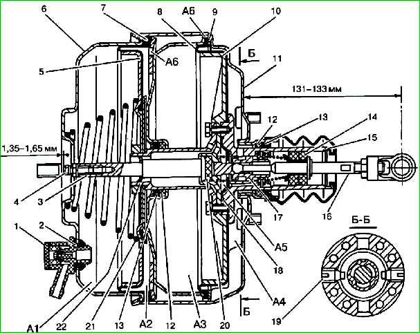
- - unscrew the piston connector nut and remove piston 5 with diaphragm 7, plate and thrust ring;
- - remove the amplifier from the device and remove the thrust cover and other parts of the amplifier from the body, remove the lock washer and remove the pusher from the connector;
- - unscrew three bolts with spring washers and remove the connector, piston 10 with diaphragm 8 and diaphragm 18 with spring.
Remove reaction rubber washer 20 from piston 10; unscrew two screws 19 securing the pusher piston 17 in the valve body 15, and remove the pusher with the piston;
- - unscrew the pusher eye, having first loosened the lock nut;
- - lightly compress the pusher spring, remove the lock washer and remove the remaining parts from the pusher.
The pusher with the piston is a permanent connection.
- - Remove the lock washers and remove the guide plastic rings 12, as well as the rubber sealing cuffs 13, from the thrust cover and amplifier housing 11;
- - remove the rubber sealing ring from the piston connector;
- - remove check valve 1 from the housing cover and replace it if necessary. Clean all parts of the amplifier from dirt and inspect.
Replace parts that are damaged or excessively worn.
Particular attention should be paid to checking the rubber parts of the amplifier, as well as the condition of the outer polished surfaces of the piston connector and valve body 15.
If there are scratches or burrs, these surfaces should be carefully cleaned with fine sandpaper and washed. If filter 14 is clogged, it must be replaced.
Before assembly, all parts of the amplifier must be absolutely clean.
If necessary, all parts, with the exception of rubber ones, can be washed in clean kerosene and dried with a stream of compressed air.
The amplifier should be assembled in the reverse order of disassembly.
When assembling, the following features must be taken into account:
- - the rubber o-ring in the valve body 15 must be lubricated with CIATIM-221 lubricant;
- - after installing the sealing collars 13 into the body and thrust cover, lubricate their internal surfaces with a thin layer of CIATIM-221 lubricant;
- - install the assembled pusher with the piston into the 15 valve body. Lightly press the pusher, overcoming the resistance of the spring, and screw in two fixing screws 19.
Tighten the screws until they stop, then unscrew them 0.5 turns each and secure them to prevent them from coming loose.
The pusher with the piston should move without jamming or distortion by 1-2 mm;
- - before assembly, lubricate the outer polished surfaces of the connector of the pistons and the housing of 15 valves with a thin layer of CIATIM-221 lubricant;
- - before assembly, cover the surface of diaphragms 7 and 8 with a thin layer of talc, and lubricate the groove of the flange of diaphragm 7 to facilitate rotation of the cover relative to the body with a thin layer of castor oil or NG-213 liquid;
- - when assembling, straighten the diaphragm 7 so that its flange goes beyond the protrusions on the amplifier body and presses against the inner diameter of the body;
- - tighten the nut securing piston 5 to a torque of 5.5-8 Nm (0.55-0.8 kgf m);
- - when inserting cover 6 into housing 11, make sure that diaphragm 7 does not wrap up.
After assembly, check the operation of the amplifier in the following order:
- - connect check valve 1 of the amplifier with a hose to a source of vacuum, for example, to the inlet pipe of a running engine; connect the end of tube 2 (see Fig. 1) in plug 5 with a hose to a vacuum gauge;
- - create a vacuum in the amplifier of about 70 kPa (0.7 kgf/cm 2) and close the valve on the vacuum pipeline. Within 10 s, the vacuum should not change by more than 4 kPa (0.04 kgf/cm 2).
After checking, set a distance of 131-133 mm between the mating surface of the amplifier body and the center of the pusher eye, as shown in Fig. 7.6 and tighten the eye nut.
Correct operation of the master brake cylinder is possible if the gap between the head of the adjusting bolt 4 and the mating plane of the vacuum booster cover 6 is 1.35-1.65 mm.
To set this gap, loosen the lock nut and rotate bolt 4. After adjustment, tighten the lock nut.
Assemble the amplifier with the master cylinder and install it on the car in the reverse order of disassembly.