Disassembling the gearbox
Clean off dirt and wash the outside of the gearbox
Unscrew the oil filler and oil drain plugs and drain the oil from the gearbox, if this has not been done previously.
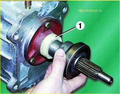
Remove the clutch release bearing and foam ring 1 from the guide sleeve.
Unscrew the bolts and remove the rear engine mount with bracket, if this was not done when removing the gearbox from the car.
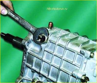
Unscrew the reverse light switch with the gasket.
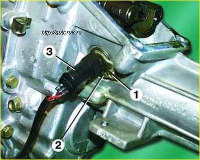
Unscrew bolt 1 securing the speedometer drive stopper, remove stopper 2 and speedometer drive 3.
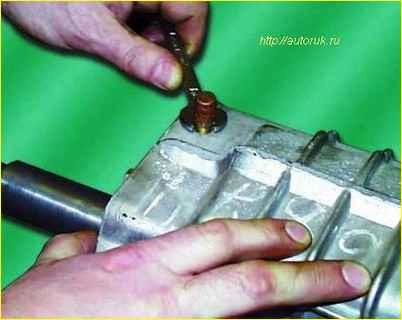
Unscrew the breather.
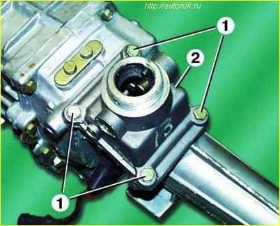
Unscrew the four bolts 1 and remove the gear shift lever housing 2 with the gasket.
Unscrew the three bolts 1 and remove the input shaft bearing cover with the guide sleeve 2 of the clutch release bearing with the gasket.
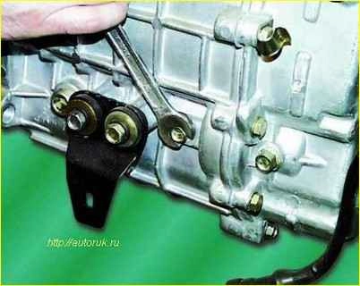
Unscrew the bolt securing the reverse idler gear axle on the front gearbox housing.
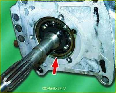
Remove the retaining ring of the input shaft bearing if necessary to replace it.
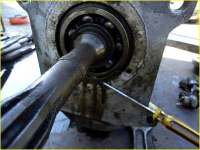
Be sure to remove the large retaining ring, otherwise you will not disconnect the box.
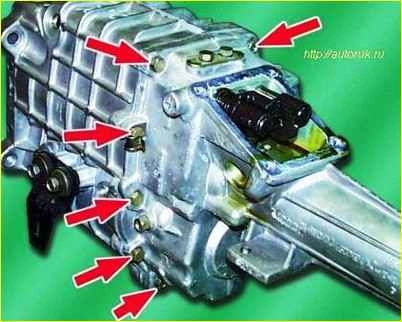
Unscrew the ten bolts securing the front gearbox housing to the rear housing.
Disconnect the front and rear gearbox housings.
To do this, you can clamp the extension in a vice with soft jaws and hit the bosses with the holes for attaching the front housing to the clutch housing with a copper hammer.
At the same time, try not to tear the gasket.
Remove the adjusting rings, if they were installed, from the seat under the front bearing of the intermediate shaft on the front gearbox housing.
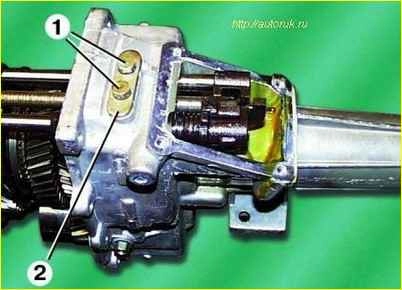
Unscrew the two bolts 1 of the fastening and remove the plate 2 of the rod clamps with the gasket.
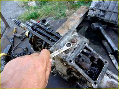
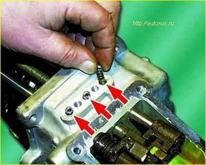
Remove the three clamp springs.
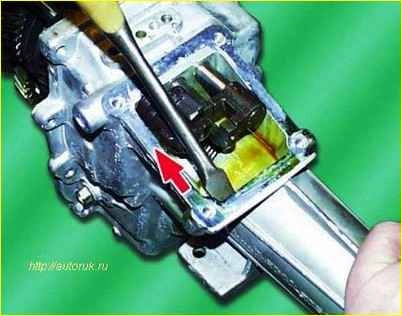
Set the 5th gear and reverse shift rod to the reverse position.
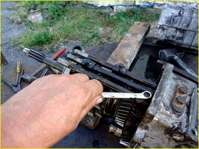
Unscrew the locking bolts securing the shift forks to the rods.
Mark the gear shift forks (their belonging to the rods and orientation). Knock out the rods with a hammer made of soft material and remove them.
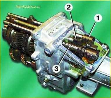
The first to remove the rod 3 for engaging the 5th gear and reverse gear, the second is the rod 1 for engaging the 1st and 2nd gears, and the last is the rod 2 for engaging the 3rd and 4th gears.
When removing the 3rd and 4th gear selector rod, be careful not to lose the locking pin installed in the rod hole.
Remove the 1st and 2nd and 3rd and 4th gear shift forks from the synchronizer sliding clutches.
Remove the retainer balls by placing your hand and pushing them with a screwdriver through the holes inside the crankcase.
Remove the two locking plungers using a special tool or a hooked wire.
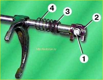
If you need to disassemble the 5th gear and reverse gear rod, you must first unscrew the locking bolt 1, and then remove the head 2, locking sleeve 3 and spring 4 from the rod.
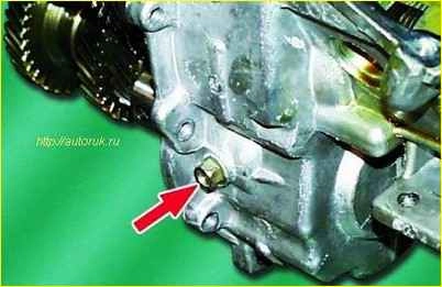
Unscrew the bolt securing the reverse intermediate gear axis on the rear gearbox housing.
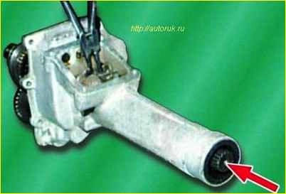
Use pliers to open the retaining ring of the rear bearing of the secondary shaft and, hitting the end with a drift of soft material, press out the secondary shaft.
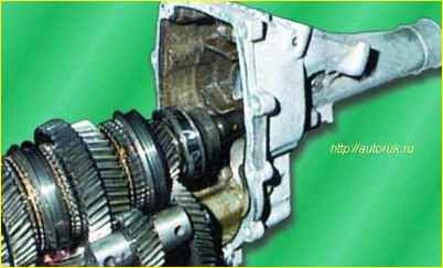
Simultaneously remove the secondary shaft assembly with the primary shaft, the intermediate shaft and the axis of the reverse intermediate gear from the rear gearbox housing.
Check that the 3rd and 4th gear synchronizer is set to neutral.
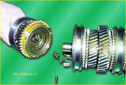
Disconnect the primary and secondary shafts, paying attention to the fact that the bulk rollers (14 pcs.) of the front bearing of the secondary shaft may fall out of the input shaft housing.
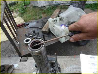
If during operation an oil leak is detected from the gearbox through the seals, the defective seals must be pressed out.
Assembling the gearbox
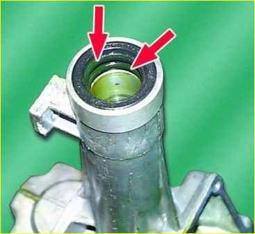
Press two oil seals into the rear crankcase extension flush with the end of the extension, if they were removed. Their working edges should be directed inside the amplifier.
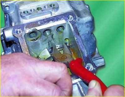
Install the retaining ring of the secondary shaft ball bearing into the groove of the rear housing, if it was removed.
Install the 5th gear and rear synchronizer sliding clutch on the secondary shaft about travel to the reverse position.
Place the input shaft onto the secondary shaft so that the bulk rollers do not fall out. At the same time, make sure that the protrusions of the blocking ring on the input shaft fit into the grooves of the 3rd and 4th gear synchronizer hub.
Connect the secondary shaft assembly with the primary one, with the gear block and the axis of the reverse intermediate gear, engaging the corresponding gears.
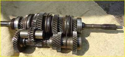
For ease of further installation, you can tie the resulting set with a rope. You can knit the set with soft knitting wire, as shown in the figure.
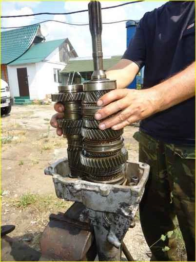
Install the rear part of the crankcase in a vertical position in a vice
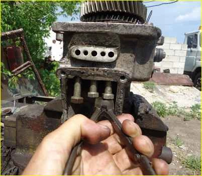
Insert a set of shafts into the rear part of the crankcase, open the retaining ring and press the ball bearings of the secondary shaft and gear block into the seats on the rear part of the crankcase, applying force alternately to the end of the 1st gear gear of the secondary shaft and the end of the intermediate shaft until until the retaining ring presses against the outer race of the ball bearing.
After this, carry out final pressing until the locking ring is seated simultaneously in the groove of the rear part of the crankcase and in the groove of the bearing. (Figure 27 shows the release of the retaining ring. The bolts are inserted to prevent the retainers from falling out. They can be removed to keep them out of the way.)
Install the axis of the reverse intermediate gear into the seat on the rear of the crankcase and tighten the fastening bolt without tightening it.
Install the rear part of the gearbox housing in a horizontal position.
Insert the shift forks of the corresponding gears into the grooves of the sliding clutches of the synchronizers.
Install locking plungers between the holes for the rods of the 3rd and 4th, 1st and 2nd and 5th gears, as well as reverse gear.
To install the plungers, it is recommended to use a mandrel and a bit, but to do this you will have to remove the plug and install a new one after installation. Therefore, it is easier to try to insert the plungers without a mandrel.
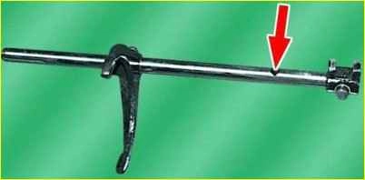
Install the locking pin into the hole of the 3rd and 4th gear shift rod.
Install the 3rd and 4th gear shift rod into the crankcase hole and the 3rd and 4th gear shift fork head. Secure the fork to the rod with a locking bolt.
Install the 1st and 2nd gear shift rod into the crankcase hole and the 1st and 2nd gear shift fork head. Secure the fork to the rod with a locking bolt.
Install the locking plunger as far as it will go into the 3rd and 4th gear shift rod.
Assemble the 5th gear and reverse shift rod if it has been disassembled.
Insert the rod into the hole in the crankcase and the hole in the 5th gear and reverse fork.
Secure the fork to the rod with a locking bolt.
When installing the rod, you must pay attention to the correct installation of the locking sleeve spring (one end must be inserted into the hole in the wall of the rear crankcase, and the other must be inserted into the recess of the locking sleeve so that the locking sleeve mustache is pressed against the head of the 5th shift rod gear and reverse).
Set the 5th gear and reverse shift rod to the neutral position.
Install the balls and springs of the clamps into the corresponding holes.
Install the rod clamp plate with the gasket in place and tighten the two bolts securing the plate.
If, during the repair of the gearbox, either one of the gearbox housings or the gear block (or its parts) was replaced, then it is necessary to determine the size of the thickness of the adjusting rings 24 in order to ensure the required axial clearance of the gear block.
After this, install a package of adjusting rings selected according to the required thickness into the ball bearing seat on the front of the crankcase.
Install the rear part of the crankcase with the shafts in a vertical position in a vice.
Install the paronite gasket.
Install the front part of the crankcase, aligning the corresponding holes with the mounting sleeves kami, and press it onto the ball bearings of the input shaft and gear block, hitting the bosses of the front part of the crankcase with a soft metal hammer.
In this case, the input shaft must be pulled upward.
Tighten ten bolts securing the front and rear crankcases evenly diagonally with a torque of 14-18 Nm (1.4-1.8 kgcm).
It should be taken into account that the two upper bolts are longer (size M8—6gx35), the remaining eight bolts are size M8—6gx30.
Install the retaining ring into the groove of the input shaft ball bearing.
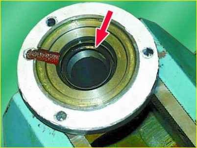
If the input shaft oil seal has been replaced, it must be pressed into the bearing cap until it stops using a mandrel.
Install the bearing cover with a gasket and tighten the three fastening bolts with a torque of 14-18 Nm (1.4-1.8 kgcm).
Insert the bolt securing the reverse intermediate gear axle into the front crankcase and finally tighten both bolts securing the axle to a torque of 44-56 Nm (4.4-5.6 kgcm).
Wrap the breather and reverse light switch with a gasket into the front crankcase.
Install the speedometer drive with the stopper into the crankcase and tighten the bolt securing the stopper.
Screw in the oil filler plug.
Install the gear shift lever housing with the gasket and tighten the four fastening bolts with a torque of 14-18 Nm (1.4-1.8 kgcm).
Lubricate the clutch release bearing guide sleeve with transmission oil.
Install the foam gasket on the guide bushing, having first lubricated the bushing with transmission oil.
Install the release bearing with clutch onto the guide sleeve.
Recommendations:
Before installing the front part of the transmission housing, you need to make sure that the forks are installed correctly.
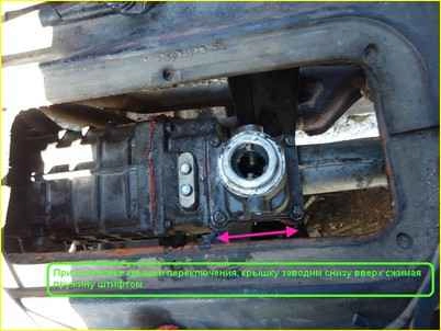
To do this, tighten the gear shift housing with two diagonal bolts. We look at the picture to see that the body is positioned correctly. And we try how we turn on all the speeds.
When turning on, slightly tighten the drive shaft. It is best to do this with an assistant.
When connecting the front and rear housings, do not forget to clean the mating surfaces from old gaskets, and before connecting, coat them with a thin layer of sealant.
Forks of the old type and the new one (with crackers (inserts)) are interchangeable.
When tightening ten bolts connecting the housings, you need to tighten all the bolts, and then tighten them diagonally.
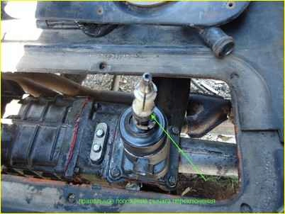
Install the gear shift lever cover without the lever itself. When installing, move it “backwards” a little so that the pin falls into place and moves the spring.
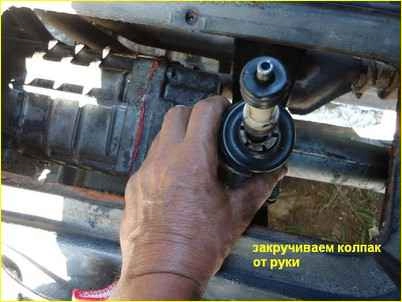
Then we install the lever itself and tighten the cap by hand, before that we put a little Litol lubricant in the rocker mechanism.


