Engine cooling system - liquid, closed, with forced circulation of liquid and expansion tank
The tightness of the cooling system allows the engine to operate at a coolant temperature exceeding 100° C, but when the coolant overheating warning light comes on, the engine must be stopped and the cause of the overheating eliminated.
The coolant level in the expansion tank on a cold engine should be at the level of the MIN mark or above it by 30-50 mm; if the liquid level is below the MIN mark, it is necessary to add coolant to the expansion tank.
In cases of frequent topping up, it is necessary to check the tightness of the system.
If there is a significant leak of liquid, it is allowed, in exceptional cases, to use water to restore its level.
However, this will inevitably reduce the density of the mixture and increase its freezing point, so the coolant should be replaced with a new one as soon as possible.
Procedure for replacing coolant:
- - place the car on a level surface;
- - remove the plug from the expansion tank;
- - open the heater tap;
- - drain the used coolant
- - first open the tap on the monoblock and after completely draining the liquid from the monoblock, open the cooling system plug (on the radiator).
Attention! To drain the coolant, a hose is installed on the faucet of the monoblock; when draining without a hose, the coolant is not completely removed from the monoblock.
flush the cooling system, filling it twice with coolant and warming up the engine to a temperature of 80-90°C;
- pour new coolant into the expansion tank 30-50 mm above the MIN mark and replace the tank cap.
To more completely remove air from the cooling system, you must:
- - remove the plug from the expansion tank;
- - open the heater tap;
warm up the engine to the opening temperature of the thermostat valve (to the operating fluid temperature of 85-95 ° C, which corresponds to the middle of the green zone of the fluid temperature indicator scale).
The opening of the thermostat valve can be determined by a noticeable increase in the temperature of the upper radiator hose when touching it with your hand.
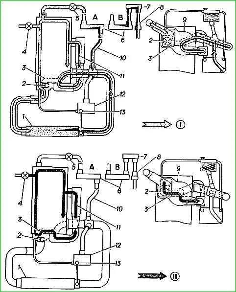
Cooling system diagram:
Do not close the expansion tank cap!
- - let the engine run for 3 - 5 minutes (in cycles) at different engine speeds: 3000 rpm 0.5 min; 1500 rpm - 0.5 min; idling - 0.5 min;
- - if necessary, add fluid and install the expansion tank cap.
Perform the final check of the fluid level on a cooled engine.
Before starting winter operation, you should check the density of the coolant, which should be in the range of 1.075-1.085 g/cm 3 at plus 20° C.
Eleven-bladed fan.
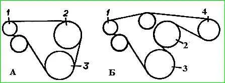
The fan drive belt is tensioned using an automatic tensioner.
No maintenance is required for the fan drive during operation.
Installation of the fan drive belt on a vehicle without power steering is shown in Figure 1.
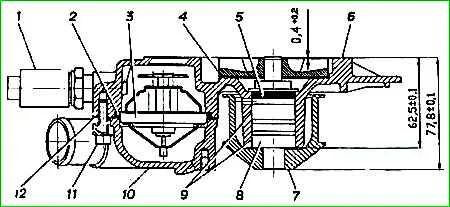
Centrifugal type water pump, the pump housing is combined with the thermostat housing 3.
The pump bearing is fixed with sealant 9 and separated from the coolant by a radial seal 5.
Lubricant is embedded in the bearing for its entire service life and no additional maintenance is required during operation.
The EATON viscous coupling is used to turn off the fan in cases of sufficient cooling of the radiator by the oncoming air flow.
The fan is turned on by a bimetallic thermal converter located on the side of the coupling facing the radiator.
As the temperature in the radiator rises, the thermal converter heats up and opens access to a special fluid into the working cavity of the coupling, and due to fluid friction, torque is transmitted from the drive disk to the driven disk on which the fan is installed.
")

")
")
")
")
")
")
")