Engine lubrication system - combined: under pressure and splash
Oil under pressure lubricates the main and connecting rod bearings of the crankshaft, camshaft bearings, thrust bearings of the crankshaft and camshaft, rocker arm bushings and the upper tips of the pushrods
The remaining parts are lubricated with sprayed oil.
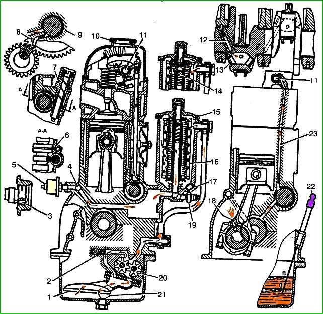
The lubrication system includes an oil pump 20 with an inlet pipe and a pressure reducing valve (installed inside the oil sump), oil channels, an oil filter with a bypass valve, an oil sump, an oil level indicator, an oil filler cap, an oil pressure indicator sensor, an alarm sensor emergency oil pressure.
The oil taken by the pump from the oil sump enters through the oil receiver through channels in the pump body and outer tube into the oil filter housing.
Next, having passed through the filter element 16, the oil enters the cavity of the second partition of the cylinder block, from where, through a drilled channel, into the oil line - longitudinal oil channel 4.
From the longitudinal channel, oil is supplied through inclined channels in the block partitions to the main bearings of the crankshaft and camshaft bearings.
The oil flowing from the fifth camshaft support into the cavity of the block between the shaft and the plug is discharged into the crankcase through a transverse hole in the shaft journal.
Oil flows to the connecting rod journals through channels 12 from the crankshaft main journals.
Oil is supplied to the rocker axis from the rear camshaft support, which has an annular groove in the middle, which communicates through channels 23 in the block, cylinder head and in the fourth main post of the rocker axis with cavity 11 in the rocker axis.
Through the holes in the rocker arm axis, oil flows to the rocker arm bushings and then through the channels in the rocker arms and adjusting screws to the upper tips of the pusher rods.
Oil is supplied to the camshaft drive gears through a tube 8 pressed into a hole in the front end of the block connected to the annular groove 9 on the first journal of the camshaft.
From the outlet of the tube, which has a small diameter, a stream of oil is ejected, directed at the gear teeth.
Through a transverse channel in the first journal of the camshaft, oil from the same groove in the journal flows to the thrust flange of the camshaft.
The oil pump drive gears are lubricated by a stream of oil ejected from channel 6 in the block connected to the fourth camshaft journal, which also has an annular groove.
The cylinder walls are lubricated by splashes of oil from the jet ejected from hole 18 in the lower head of the connecting rod when this hole coincides with the channel in the crankshaft journal, as well as oil flowing from under the crankshaft bearings.
All other parts (valve - its stem and end, drive shaft of the oil pump and ignition distributor, camshaft cams) are lubricated with oil flowing from the gaps in the bearings and splashed by moving engine parts.
Lubricant system capacity - 6 l.
Oil is poured into the engine through the oil filler neck located on the rocker cover and closed with a cover with a rubber seal.
The oil level is controlled by the “P” and “O” marks on the level indicator rod. The oil level should be maintained between the “P” and “O” marks.
The pressure in the lubrication system at average vehicle speeds (approximately 50 km/h) should be 200-400 kPa (2-4 kgf/cm 2).
It can rise on a cold engine to 450 kPa (4.5 kgf/cm 2) and drop in hot weather to 150 kPa (1.5 kgf/cm 2).
Reducing oil pressure at an average rotation speed below 100 kPa (1 kgf/cm 2) and at low idle speed - below 50 kPa (0.5 kgf/cm 2) indicates a malfunction in the lubrication system or excessive wear crankshaft and camshaft bearings.
Further operation of the engine under these conditions must be stopped.
Oil pressure is determined by a gauge on the instrument panel, the sensor of which is screwed into the oil filter housing.
In addition, the system is equipped with an oil pressure warning lamp, the sensor of which is screwed into the hole in the bottom of the filter.
The warning lamp is located on the instrument panel and glows red when the pressure in the system drops below 40-80 kPa (04-0.8 kgf/cm 2).
You cannot operate a vehicle with the emergency oil pressure lamp illuminated.
Only short-term illumination of the lamp is permissible at low idle speed and during braking.
If the system is working properly, then with a slight increase in rotation speed the lamp goes out.
If the oil pressure is too low or too high from the above values, you should first check the serviceability of the sensors and indicators.
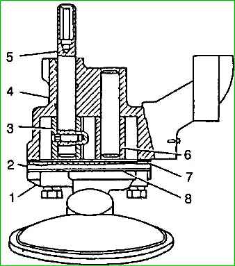
The gear-type oil pump is installed inside the oil sump.
The pump is attached with two studs to inclined platforms on the third and fourth partitions of the cylinder block.
Precision installation of the pump is ensured by two bushing pins pressed into the cylinder block.
Pump body 4 is cast from aluminum alloy, gears 3 and 6 have straight teeth and are made of cermet (sintered metal powder).
Drive gear 3 is secured to roller 5 with a pin.
At the upper end of the roller there is a hexagonal hole into which the oil pump drive shaft fits.
Driven gear 6 rotates freely on an axis pressed into the pump housing.
Pump cover 2 is made of gray cast iron and is attached to the pump with four bolts.
A cardboard gasket 0.3 mm thick is placed under the cover.
The oil receiver and the inlet pipe 1 of the oil pump are made in a single housing made of aluminum alloy. The receiving part of the pipe has a rolled mesh.
The pipe is attached to the oil pump with four bolts together with the oil pump cover through a paronite gasket 8.
The performance of the oil pump is significantly higher than that required for the engine.
The capacity reserve is necessary to ensure adequate oil pressure in the system at any engine operating mode.
Excess oil flows from the discharge cavity of the pump through the pressure reducing valve back into the suction cavity.
When the oil flow increases through the gaps in the bearings (if the engine wears out), the required pressure is also maintained in the system, but in this case a smaller amount of oil passes through the pressure reducing valve back into the receiving cavity of the pump.
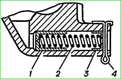
A plunger-type pressure reducing valve is located in the oil pump housing. The end of plunger 1 is subject to oil pressure, under the influence of which the plunger moves, overcoming the force of spring 2.
When a certain pressure is reached, the plunger opens the hole in the drain channel, allowing excess oil to flow into the receiving cavity of the pump.
The pressure reducing valve spring rests on a flat washer 3 and is secured with a cotter pin 4, passed through the holes in the boss on the pump body.
The pressure reducing valve is not adjustable; the required pressure characteristic is provided by the geometric dimensions of the pump housing and the characteristics of the spring: to compress the spring to a length of 40 mm, a force in the range of 435-48.5 N (435-485 kgf) is required.
In operation, it is not allowed to change the spring force of the pressure reducing valve in any way.
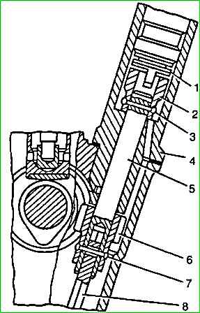
The oil pump and ignition distributor are driven from the camshaft by a pair of helical gears.
The drive gear is steel, cast into the body of the cast iron camshaft.
Driving gear 8 is steel, heat-strengthened, pinned to a roller 5 rotating in a cast iron housing.
The upper end of the roller is equipped with a sleeve 2 having aslot (displaced 1.15 mm from the axis of the roller) for driving the ignition distributor sensor.
The bushing on the shaft is secured with a pin 3. A hexagonal shaft 10 is pivotally connected to the lower end of the shaft, the lower end of which fits into the hexagonal hole of the oil pump shaft.
When rotating, gear 8 is pressed against the end of the cast iron drive housing through thrust washers 6 and 7.
Lubrication of this unit, as well as the roller in the drive housing, is carried out by oil sprayed by the drive gears and flowing down the wall of the block.
The oil flowing down the walls enters the slot (trap) at the lower end of the drive housing and then through the hole onto the surface of the roller.
In the hole for the roller in the drive housing, a spiral groove is cut, along which the oil rises up when the roller rotates and is evenly distributed along its entire length.
Excess oil from the upper cavity of the drive housing is discharged back into the crankcase through the drain hole in the housing.
The correct position of the ignition distributor sensor on the engine is ensured by installing the drive in the block in such a way that when the piston of the first cylinder is at TDC (compression stroke), the slot on the drive sleeve is parallel to the engine axis at the maximum distance from it.
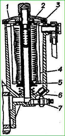
The oil purification filter is full-flow, with paper or cotton replaceable filter elements. All the oil pumped into the system passes through the filter.
The following filter elements are used for these engines: NAMI-VG-10, REGOTMAS-412-1-05 and REGOTMAS-412-1-06.
The filter consists of a housing, a cover 1 central rod with a bypass valve and a filter element 4.
The filter housing is made of aluminum alloy and is attached to the cylinder block through a paronite gasket with four studs.
The central rod is tightly screwed into the body. The upper end of the rod has a thread for the nut securing the filter cover.
A plug 6 is screwed into the housing from below to drain settled contaminants.
Emergency oil pressure sensor 7 is screwed into the boss in the lower part of the housing.
Filter cover 1 is made of aluminum alloy. It is secured with a cap nut screwed onto the threaded end of the central rod protruding from the cover.
There is a rubber sealing gasket in the groove of the cover. The cover nut is sealed with a copper gasket.
The central filter rod is hollow.
In its upper part there is a bypass valve, consisting of a textolite plate of the valve seat, a spring and a spring stop.
The rod has four rows of holes drilled for oil passage; The top row is located above the valve and above the filter element.
In the normal state of the element, its resistance is low, about 10-20 kPa (0.1-0.2 kgf/cm 2), and all the oil passes through it, as shown in the diagram with arrows .
From the filter element, the purified oil passes through the holes into the rod and further into the lubrication system.
When the element becomes clogged, its resistance increases, and when the pressure reaches 70–90 kPa (0.7–0.9 kgf/cm 2), the bypass valve opens and begins to let oil through.
When installed in the housing, the ends of the filter element from the bottom and top are sealed with rings 2 and 5 made of oil-resistant rubber, tightly covering the central rod.
Sealing at the ends is ensured by a spring and a support washer, pressing the element to the end of the lid boss.