To turn the car's electrical circuits on and off, use the ignition switch or simply the ignition switch
The ignition switch has a mechanical anti-theft device that blocks steering wheel rotation.
The locking rod of the anti-theft device extends when the key is placed in the “parking” position and removed from the lock.
After this, turn the steering wheel so that the rod fits into the groove on the steering shaft, locking it.
The locking rod is recessed, releasing the shaft, when the key is turned from the “parking” position to the “off” position.
The closure of the ignition switch contacts at various key positions and the switched circuits are shown in the table.
Always on (regardless of the position of the key in the ignition switch) are the power circuits for the horn, brake light, hazard lights, cigarette lighter, lamp, plug socket for a portable lamp and high beam headlight alarm.
Removing the ignition switch
Disconnect the negative cable from the battery.
Remove the steering column covers.
We mark the wires suitable for the contact part of the ignition switch and disconnect them.
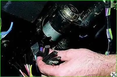
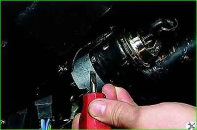
Using a slotted screwdriver, unscrew one screw securing the ignition switch to the steering column bracket on the left and the second, located below, to the right of the first.
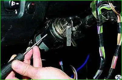
Putting the ignition switch key in position “0” (“off”), use a slotted screwdriver with a narrow blade to push the ignition switch lock through the hole in the side wall of the steering column bracket.
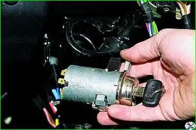
Pulling towards you, remove the ignition switch.
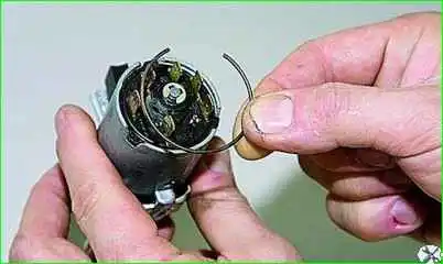
To replace the contact part of the ignition switch, pry it up with a screwdriver and remove the retaining ring.
The snap ring may come off.
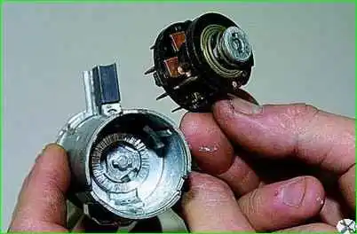
Remove the contact part of the ignition switch.
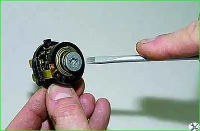
When installing a new contact part, turn its rotating part counterclockwise with a slotted screwdriver until it stops.
Remove the key from the ignition switch and insert the contact part into the housing so that the wide protrusion of the contact part coincides with the wide cavity of the housing.
Assemble the ignition switch in the reverse order.
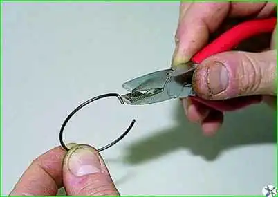
To facilitate installation of the retaining ring, use pliers to bend the tendril

Closing the ignition switch contacts
In the key position (III) (parking), the contacts are energized “30” – “INT”
In the key position (0), contacts “30/1”, “30”, “30/1”, “30” - “INT” are energized
In the key position (I), contacts “30/1” – “15” are energized and the circuits are switched on:
- Generator excitation winding.
- Ignition system*.
- External lighting.
- Instrument lighting.
- Low and high beam headlights.
- Fog light.
- Windshield and tailgate glass cleaners.
- Control unit
- carburetor solenoid valve*.
- Control system engine (including electric fuel pump and engine cooling system fans)**.
- Heated tailgate glass.
- Washer.
- Heater fan.
- Direction indicators. Reversing light
- Control devices.
In the key position (II), contacts “30/1” – “15”, “30” – “50”, “30” – “INT” are energized and the starter is turned on
* Only for VAZ-21213 engine.
** Only for VAZ-21214 engine.


