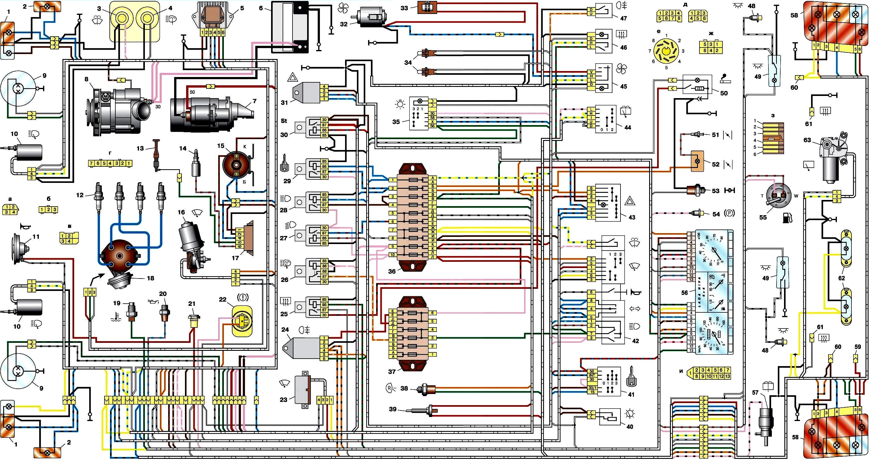
Electrical diagram of the VAZ-21213 car
Scheme details: 1 – front lights; 2 – side direction indicators; 3 – windshield washer electric motor; 4 – headlight washer electric motor*; 5 – switch; 6 – battery; 7 – starter; 8 – generator; 9 – headlights;

10 – gearmotors for headlight cleaners*; 11 – sound signal; 12 – spark plugs; 13 – carburetor limit switch; 14 – carburetor solenoid valve; 15 – ignition coil; 16 – windshield wiper gearmotor; 17 – carburetor solenoid valve control unit; 18 – ignition distributor sensor; 19 – coolant temperature indicator sensor; 20 – oil pressure warning lamp sensor; 21 – plug socket for a portable lamp**; 22 – brake fluid level warning lamp sensor; 23 – windshield wiper relay; 24 – relay for turning on the rear fog light***; 25 – relay for turning on the heated rear window; 26 – relay for turning on headlight cleaners and washer*; 27 – relay for turning on low beam headlights; 28 – relay for turning on the high beam headlights; 29 – ignition relay; 30 – starter activation relay; 31 – relay-breaker for alarm and direction indicators; 32 – heater electric motor; 33 – additional resistor of the heater electric motor; 34 – backlight lamps for heater control levers; 35 – external lighting switch; 36 – main fuse block; 37 – additional fuse block; 38 – reverse light switch; 39 – brake light switch; 40 – instrument lighting regulator; 41 – ignition switch; 42 – three-lever switch; 43 – alarm switch; 44 – tailgate glass cleaner and washer switch*; 45 – heater motor switch; 46 – switch for heating the rear door glass; 47 – rear fog light switch; 48 – lamp switches located in the door pillars; 49 – interior lamps; 50 – cigarette lighter; 51 – switch for the warning lamp for covering the carburetor air damper; 52 – control lamp for covering the carburetor air damper; 53 – switch for differential lock warning lamp; 54 – parking brake warning lamp switch; 55 – sensor for level indicator and fuel reserve; 56 – instrument cluster; 57 – tailgate glass washer motor; 58 – rear lights; 59 – block for connecting additional brake lights; 60 – blocks for connecting side marker indicators; 61 – pads for connecting to the heated glass element of the tailgate; 62 – license plate lights; 63 – rear door glass wiper motor.
The order of conditional numbering of plugs in the blocks: a – windshield wipers, headlights and tailgate glass, windshield wiper relay breaker; b – ignition distributor sensor; c – relay-interrupter for alarm and direction indicators; g – switch; d – three-lever switch; e – hazard warning switch; g – relay for turning on the rear fog light; h – rear lights (pin numbering in order from top to bottom); and – instrument clusters.
In the instrument panel wiring harness, the second ends of the white wires are brought together to one point, which is connected to the instrument lighting control.
The second ends of the black wires are also brought together to a point connected to ground.
The second ends of the yellow wires with a blue stripe are brought together to a point connected to terminal “A” of the main fuse block.
And the second ends of the orange wires are also brought together to a point connected to terminal “B” of the main fuse block.
* Installed on parts of manufactured vehicles;
** not installed since 2000;
*** installed since 2001. Previously, the rear fog light was switched on directly by switch 47, powered by fuse 3 of the additional fuse box.