Open the hood and use a 10 mm spanner to disconnect the negative battery terminal
Remove the air filter in accordance with the article - "Removing engine intake components"
Disconnect block 1, Figure 1, of the front left wiring harness from the brake fluid level sensor.
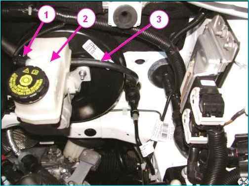
Removing the brake booster: 1 - block of the front left wiring harness; 2 - reservoir; 3 – hose to the clutch master cylinder
Pump out the brake fluid from reservoir 2, disconnect hose 3 of the clutch master cylinder from the reservoir nipple and install plugs in the hose hole and on the reservoir nipple.
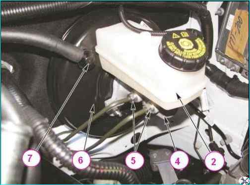
Removing the brake booster: 2 - reservoir; 4 - brake master cylinder; 5 – brake pipe nipples; 6 - brake booster; 7 - brake booster hose nipple
Disconnect the brake pipe nipples 5, Figure 2, from the brake master cylinder 4, move the pipes to the side and install technological plugs in the holes of the master cylinder and on the brake pipes.
Disconnect the nipple 7 of the hose from the vacuum booster 6.
Remove the cover of the fuse box in the passenger compartment and disconnect the instrument panel wiring harness connectors from the trunk lock drive switch and from the headlight corrector.
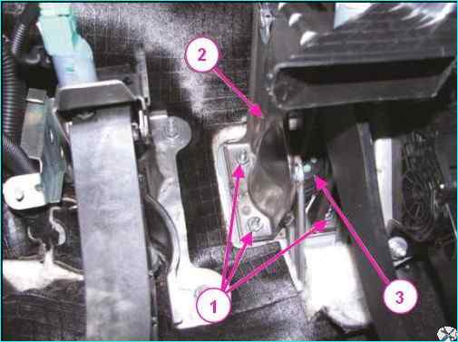
Disconnect connector 1, Figure 2, of the instrument panel wiring harness from the electronic accelerator pedal 4, use a 13 mm head to unscrew the two nuts 3 securing the accelerator pedal bracket and remove the bracket 2 with the pedal accelerator assembly.
Disconnect connector 1, Fig. 3, from the brake light switch.
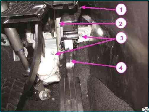
Removing the accelerator pedal bracket: 1 - instrument panel harness connector; 2 - accelerator pedal bracket; 3 - accelerator pedal bracket mounting nuts; 4 – electronic accelerator pedal
Turn the brake signal switch 2 to 0 counterclockwise and remove it from the hole in the brake pedal bracket 7.
Using a flat-head screwdriver, remove the bracket 6 and remove the axle 4 from the holes in the fork 5 of the brake booster rod and the brake pedal 3.
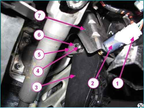
Disconnecting the brake booster rod: 1 – instrument panel harness connector; 2 – brake signal switch; 3 – brake pedal; 4 - axle connecting fork of brake booster rod and brake pedal; 5 - fork of brake booster rod; 6 - axle fixing bracket; 7 - Brake pedal bracket
Using a 13 mm head, unscrew the four nuts 1, Fig. 4, securing the vacuum booster to the front shield and remove the vacuum booster 3 with the brake master cylinder and reservoir assembly.
Installation
Install the brake booster on the front shield.
Install the bracket 2, Fig. 5, of the brake pedal on the studs of the brake booster, tighten it and using a 13 mm head tighten the four nuts 1 securing the vacuum booster.
Tightening torque of the mounting nuts is 18 - 24 Nm (1.8 - 2.4 kgf.m).
Removing the brake booster: 1 - brake booster mounting nut; 2 - brake pedal bracket; 3 - brake booster
Install the connecting axle 4, figure 3, into the holes in the fork 5 of the brake booster rod and the brake pedal 3 and secure it with the bracket 6.
Pull the rod out of the brake light switch, ensuring a size of 10 mm, as shown in figure 5.
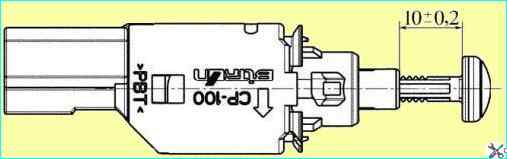
Installing the brake light switch rod
Install the brake light switch into the hole in the brake pedal bracket and turn it clockwise until it stops.
When installing the brake light switch, the brake pedal must be in the upper position.
Attacht block 1, Fig. 3, of the instrument panel wiring harness to the brake light switch 2.
Install bracket 2, Fig. 2, of the accelerator pedal with the pedal 4 in assembly, tighten and tighten the two nuts 3 of the bracket fastening.
Tightening torque of the nuts is 18 - 24 Nm (1.8 - 2.4 kgf.m).
Connect block 1 of the instrument panel wiring harness to the electronic accelerator pedal.
Connect the blocks of the instrument panel wiring harness to the trunk lock drive switch and to the headlight corrector and install the fuse box cover in the passenger compartment of the car.
Apply soapy water to fitting 7, Fig. 1, of the hose and install the fitting in the hole of the vacuum booster.
Remove the plugs from brake pipes and holes of the brake master cylinder, connect the brake pipes to the brake master cylinder 4, Fig. 2, and tighten the fittings 5.
Tightening torque of the fittings 14 - 20 Nm (1.4 - 2.0 kgf.m) (key 13 for brake pipes, replaceable insert 13, torque wrench).
Connect block 1, Fig. 1, of the front left wiring harness to the brake fluid level sensor.
Remove the plugs from the reservoir fitting and the opening of the clutch master cylinder hose, install hose 3, Fig. 1, on the reservoir fitting 2.
Install the air filter and resonator on the car.
Connect the negative cable terminal to the battery.
Fill the reservoir with brake fluid up to "max" mark on the reservoir body and bleed the brake system and clutch hydraulic drive.
Check the efficiency of the working brake system.