Replacing elements of the multimedia and navigation systems of the Lada Vesta
The Lada Vesta is equipped with a radio receiver and audio player or is equipped with multimedia navigation equipment
The work on removing and installing these devices is the same.
Prepare the car for work.
Lift the hood and disconnect the negative terminal from the battery.
Disconnect the central trim 1, Figure 1, from the instrument panel 2, overcoming the resistance of the clamps.
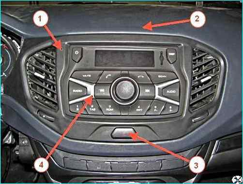
Removing the central instrument panel trim: 1 - central instrument panel trim; 2 - instrument panel; 3 - hazard warning button; 4 – radio and audio player
Disconnect the instrument panel wire harness connector from the connector of the hazard warning button 3, installed on the central trim, and remove the central trim of the instrument panel.
Using a T20 bit and a screwdriver, unscrew the four screws 1, Figure 2, self-tapping and remove the central nozzle 2 of the body ventilation.

Removing the central nozzle of the body ventilation: 1 - self-tapping screw; 2 - central nozzle of the body ventilation; 3 - radio receiver and audio file player
Using a T20 bit and a screwdriver, unscrew the four screws 1, Figure 3, self-tapping and remove the radio receiver and audio file player 2 from the socket of the instrument panel 3.
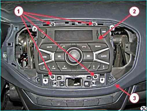
Removing the radio receiver and audio file player: 1 - self-tapping screw; 2 - radio receiver and audio file player; 3 - instrument panel
Disconnect connectors 1 and 2, Figure 4, of the instrument panel wire harness from the radio and audio player connectors 5.
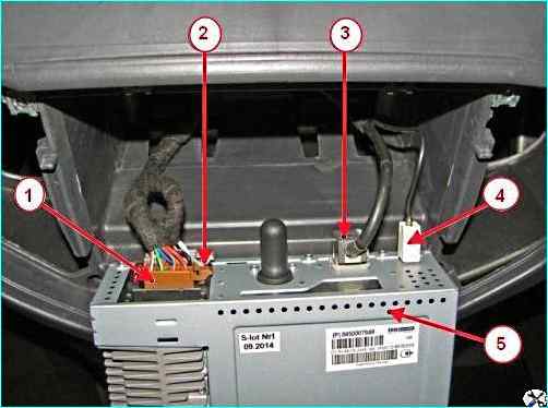
Disconnecting connectors and connectors of the wire harness from the radio and audio player: 1, 2 - connector of the instrument panel wire harness; 3 - USB cable connector; 4 - antenna cable connector; 5 - radio receiver and audio file player
Disconnect connectors 3 of the USB cable and 4 of the antenna cable from the connectors of the radio receiver and audio file player.
Disconnect the connector of the cable of the multimedia system control unit on the steering wheel (if available) from the connectors of the radio receiver and audio file player.
After this, remove the radio receiver and audio file player.
Install the radio receiver and audio file player in the reverse order of removal.
When installing the radio receiver in the instrument panel socket, check that the wires go into the corresponding holes in the instrument panel in order to avoid pinching them.
Removing and installing the antenna
Remove the lamp 1, Figure 5, of the interior lighting in accordance with the article "Removal and installation lampshades".
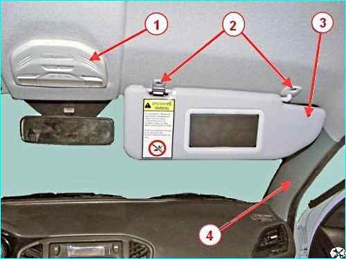
Removing the antenna: 1 - interior light lamp; 2 - screw; 3 - right sun visor; 4 - right windshield pillar trim
Using a T20 bit and a screwdriver, unscrew the two screws 2 and remove the right sun visor 3.
Using a flat screwdriver, remove the trim 4 of the right windshield pillar, overcoming the resistance of the holders.
Disconnect connectors 1 and 2, Figure 6, of the antenna cable from the connectors of harness 5 of the instrument panel.
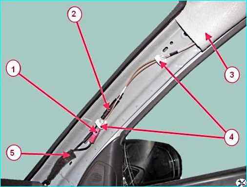
Antenna cable fastening elements: 1 - navigation system antenna cable connector; 2 - radio antenna cable connector; 3 - roof trim; 4 - antenna cable fastening element; 5 - instrument panel wire harness
Remove the antenna cable from the two fastening elements 4 on the right windshield pillar.
Using a screwdriver, remove the two plugs 1, Figure 7, of the right front handrail.
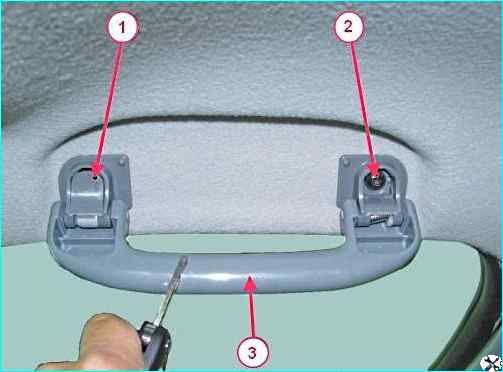
Fastening the right front handrail: 1 - plug; 2 - screw; 3 - right front handrail
Using a T20 bit and a screwdriver, unscrew the two screws 2 and remove the right front handrail 3.
Using a 22 head, unscrew the nut 1, Figure 8, fastening the antenna to the roof panel, remove the washer 2.
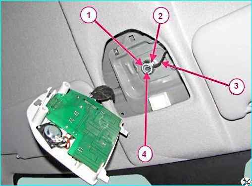
Antenna fastening elements: 1 - antenna fastening nut; 2 - washer; 3 - antenna cable; 4 - antenna
Carefully bend back the right front part of the roof trim, avoiding bending the trim.
Using a flat-head screwdriver, disconnect the two clamps securing the antenna cable to the body.
Remove antenna 1, Figure 9, from hole 3 in the roof panel together with antenna cable 2.
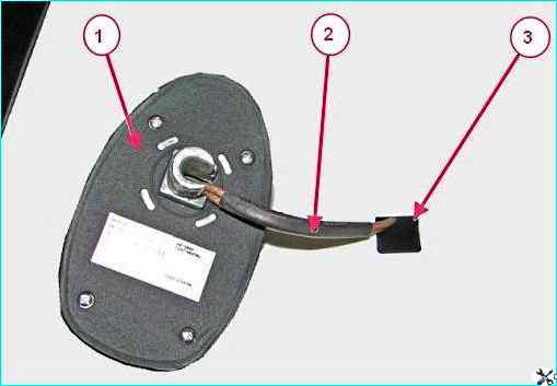
Antenna mounting elements (view from the roof): 1 - antenna; 2 - antenna cable; 3 - holes in the roof panel for installing the antenna
Install the antenna with the antenna cable assembly in the reverse order of removal.
Removal and installation of speakers is discussed in the article on door repair.
Removal and installation (CBCE) of the central body electronics unit
Prepare the car for work.
Disconnect the negative terminal of the battery.
Remove the body of the glove compartment of the instrument panel
Disconnect from CBCE 1, Figure 1, four connectors 2 of the instrument panel wire harness.

Installing the CBKE on a vehicle (view of the instrument panel from the engine compartment): 1 - CBKE; 2 - instrument panel wire harness connector; 3 - nut; 4 - instrument panel glove compartment housing; 5 - instrument panel crossbar bracket; 6 - instrument panel
Using an 8 mm head, unscrew the nut 3 securing the CBKE to the bracket 5 of the instrument panel crossbar 6.
Disconnect the CBKE unit from the bracket of the instrument panel crossbar and remove it from the car.
Install the CBKE on the car in the reverse order of removal.
Removing and installing the ERA GLONASS unit
Prepare the car for work. Disconnect the negative terminal of the battery.
Remove the body of the glove compartment of the instrument panel.
Disconnect two connectors 2 of the instrument panel wire harness from unit 1, Fig. 11, "ERA GLONAS".
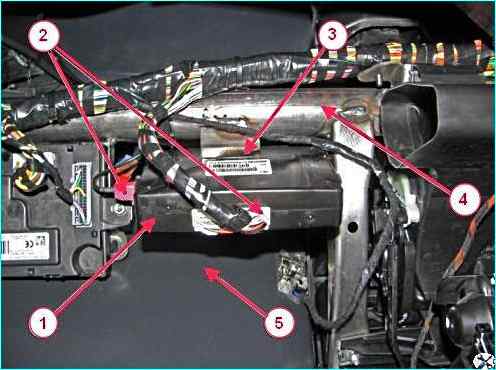
Installing the "ERA GLONAS" unit on the car (view of the instrument panel from the engine compartment): 1 - "ERA GLONAS" unit; 2 - instrument panel wire harness connector; 3 - instrument panel crossbar bracket; 4 - instrument panel crossbar; 5 - instrument panel storage compartment body
Disconnect the "ERA GLONASS" unit from bracket 3 of crossbar 4 of the instrument panel and remove it from the car.
Install the "ERA GLONASS" unit on the car in the reverse order of removal.


