Removing and installing the ABS hydraulic unit
Prepare the car for work.
Place the car on a lift, apply the parking brake and turn off the ignition.
Open the hood and disconnect the negative battery terminal.
Disconnect the plug 1, Figure 1, of the front wiring harness from the ABS hydraulic unit 7.
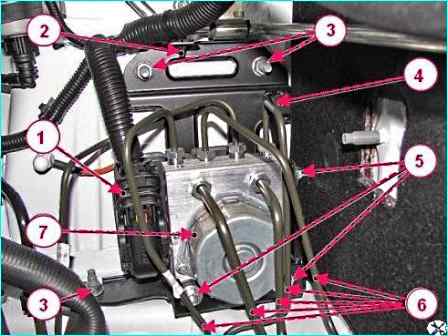
Removing the hydraulic unit ABS: 1 - front wire harness connector; 2 - front wire harness fastening clip on hydraulic unit bracket; 3 - hydraulic unit bracket fastening nut; 4 - hydraulic unit fastening bracket; 5 - hydraulic unit fastening nut on bracket; 6 - brake pipe; 7 - ABS hydraulic unit
Using a brake pipe wrench, disconnect the brake pipes 6 from the ABS hydraulic unit.
Install plugs in the holes in the hydraulic unit and on the brake pipes.
Using pliers, disconnect the clamp 2 of the wire harness from the bracket 4 of the hydraulic unit.
Using a flat-head screwdriver, remove the brake pipes 6 from the mounting brackets on the body.
Using a 13 mm head, unscrew the three nuts 3 securing the hydraulic unit bracket to the body and remove the hydraulic unit 7 assembled with the bracket 4 of the mounting.
Using a 10 mm head, unscrew the three nuts 5 securing the hydraulic unit to the mounting bracket and remove the hydraulic unit with bracket.
Installing the ABS hydraulic unit
After replacing the hydraulic unit, you will need to perform the ABS ECU parameter programming procedure.
Install the hydraulic unit 7 on the bracket 4 and secure it with three nuts 5. The tightening torque of the nuts 7 is 9 Nm (0.7-0.9 kgf.m).
Install the hydraulic unit assembled with the bracket on the vehicle and secure it with three nuts 3. The tightening torque of the nuts is 18 - 24 Nm (1.8 - 2.4 kgf.m).
Connect the plug 1 of the front wiring harness to the hydraulic unit connector.
Secure the retainer 2 of the wiring harness on the bracket 4 of the hydraulic unit.
Secure the brake pipes 6 in brackets for fastening on the body.
We remove the technological plugs from the holes of the hydraulic unit and brake pipes and connect the brake pipes to the hydraulic unit. Tightening torque of brake pipe fittings 14 - 20 Nm (1.4 - 2.0 kgf.m).
Connect the negative terminal to the battery.
Removing and installing the front wheel speed sensor
Prepare the car for work.
Place the car on a lift, apply the parking brake and turn off the ignition.
Open the hood and disconnect the negative terminal of the battery.
Raise the car to a height convenient for work.
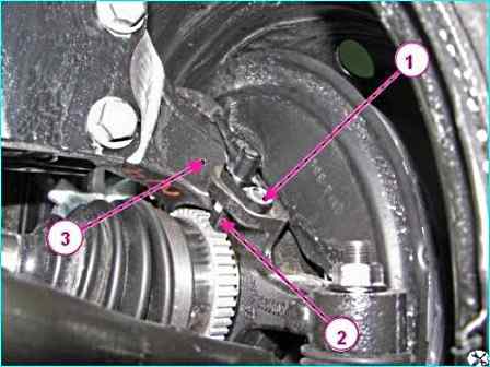
Removing the front wheel speed sensor: 1 - speed sensor mounting screw; 2 - front wheel speed sensor; 3 - steering knuckle
Using a TorxT30 replacement bit, unscrew screw 1, Figure 2, for mounting the speed sensor and remove speed sensor 2 from the hole in steering knuckle 3.
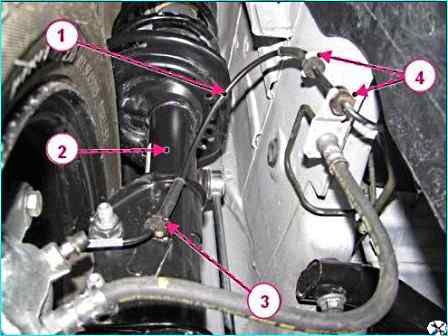
Disconnecting the front wheel speed sensor wiring harness: 1 - front wheel speed sensor wiring harness; 2 - front suspension strut; 3 - bracket for fastening the speed sensor wiring harness on the front suspension strut 4 - bracket for fastening the speed sensor wiring harness on the engine compartment mudguard
Remove harness 1, Figure 3, of the speed sensor wires from the slots of bracket 3 on the front suspension strut and brackets 4 on the engine compartment mudguard.
Disconnect the speed sensor wiring harness connector from the front wiring harness and the retainer on the car body and remove the speed sensor.
Installing the front wheel speed sensor
Connect the speed sensor wiring harness connector to the front wiring harness and the retainer on the car body.
Install sensor 2, Figure 2, of the speed sensor in the mounting hole on the steering knuckle 3 and secure with a screw 1. Tightening torque of the screw 6 - 7 Nm (0.6 - 0.7 kgf.m).
Install harness 1, Figure 3, of the speed sensor wires into the groove of bracket 3 of the front suspension strut and into the grooves of brackets 4 on the mudguard of the engine compartment.
Removing and installing the rear wheel speed sensor
Prepare the car for work.
Install the car on a lift, braking ue the parking brake and turn off the ignition.
Open the hood and disconnect the negative battery terminal.
Remove the rear wheel.
Raise the car to a height convenient for performing work.
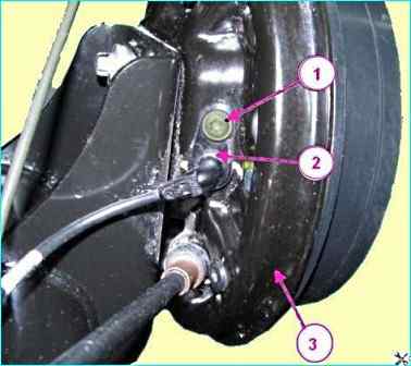
Removing the rear wheel speed sensor: 1 - speed sensor mounting screw; 2 - rear wheel speed sensor; 3 - rear brake shield
Using a TorxT30 bit, unscrew screw 1, Fig. 4, securing speed sensor 2 to rear brake shield 3 and remove the sensor.
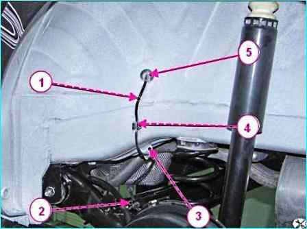
Disconnecting the rear wheel speed sensor wiring harness: 1 - rear wheel speed sensor wiring harness; 2 - speed sensor wiring harness mounting bracket on the rear suspension arm; 3 - speed sensor wiring harness mounting bracket on the body; 4 - speed sensor wiring harness mounting bracket on the body; 5 - plug
Using a flat-head screwdriver, remove harness 1, Figure 5, of the speed sensor wires from the groove of bracket 2 and the mounting bracket on the rear suspension arm, from the groove of bracket 3 and the mounting bracket 4 on the body.
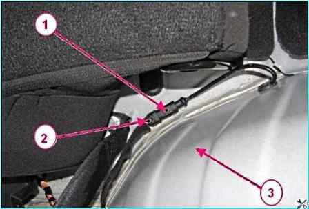
Disconnecting the speed sensor wire harness from the rear wire harness (top view): 1 - speed sensor wire harness connector; 2 - rear wire harness connector; 3 - rear wheel arch
Using a slotted screwdriver, remove plug 5 of the speed sensor wiring harness from the hole in the rear wheel arch.
Remove the rear wheel arch trim from the interior side.
Disconnect connector 1, Figure 6, of the speed sensor harness from harness 2 of the rear wires and the body mounting clamp and remove the speed sensor.
Installing the rear wheel speed sensor
Insert connector 1, Figure 6, of the speed sensor wiring harness into the hole in arch 3 of the rear wheel and connect it to the body mounting clamp and connector 2 of the rear wiring harness.
Install plug 5, Figure 5, of the speed sensor wiring harness into the hole in the rear wheel arch wheels.
Install the rear wheel arch trim from the interior side.
Install the speed sensor 2, Figure 4, in the hole in the brake shield 3 and secure it with screw 1. The tightening torque of the screw is 6 - 7 Nm (0.6 - 0.7 kgf.m).
Install the harness 1, Figure 5, of the speed sensor wires in the groove of bracket 2 and the mounting bracket on the rear suspension arm, in the groove of bracket 3 and the mounting bracket 4 on the body.
Install the rear wheel.


