Removing and installing the handbrake lever
Prepare the car for work and turn off the ignition.
Remove the floor tunnel trim.
Disconnect the wiring harness block from the handbrake lever indicator light switch.
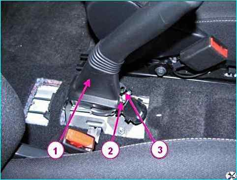
Disconnecting the handbrake lever cables: 1 - handbrake lever; 2 – equalizer cable adjusting nut; 3 – equalizer cable of hand brake lever
Using a 10 mm wrench, loosen the adjusting nut 2, Figure 1, of the equalizer cable of the hand brake lever and disconnect both cables 1, Figure 2, from equalizer 2.
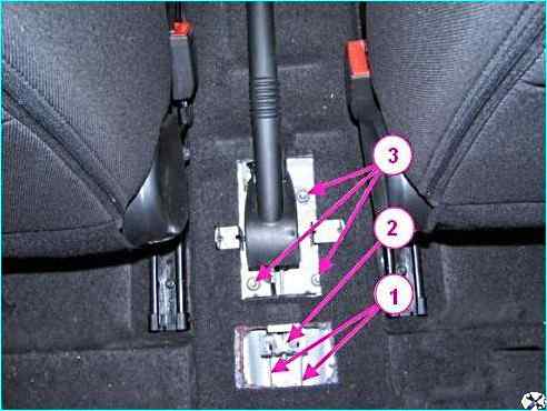
Removing the hand brake lever: 1 – hand brake lever torsions; 2 - cable equalizer; 3 - nuts for fastening the hand brake lever
Installing the lever
Install the hand brake lever on the mounting studs and secure with three nuts 3, Figure 2. The tightening torque of the nuts is 18 - 24 Nm (1.8 - 2.4 kgf.m).
Install the cables 1 of the hand brake drive into the holes of the equalizer 2.
Tighten the adjusting nut 2, Figure 1, of the equalizer cable so that the size from the upper end of the adjusting nut to the end of the threaded part of the equalizer cable is 16 ± 0.3 mm.
Connect the wiring harness block to the switch of the hand brake lever signal lamp brake drive.
Install the floor tunnel lining.
Adjusting the hand brake drive
Place the car on a lift, apply the parking brake and turn off the ignition.
Lower the hand brake drive lever.
Tighten and lower the hand brake drive lever to its original position five times to bring the drive cables into working condition.
Lift the car until the wheels are off the ground and make sure that the rear wheels are rotating.
If this is not the case, check the following elements and, if necessary, repair or replace them:
- - hand brake drive cables;
- - rear brake wheel cylinders;
- - automatic adjustment mechanisms gap.
Using a 10 mm wrench, loosen the adjusting nut 2, Figure 1, to tighten the cables.
Install the hand brake lever on the second notch of the toothed sector.
Tighten the adjusting nut so that the rear wheels stop rotating manually.
Tighten and lower the hand brake lever 2-3 times and check the rotation of the rear wheels.
If the wheels do not rotate, gradually loosen the adjusting nut until the wheels begin to rotate freely.
Local contact of the friction lining with the working surface of the drum is allowed.
Check the efficiency of the working brake system.
Replacing the hand brake cable
Prepare the car for performing work.
Place the car on a lift, apply the handbrake and turn off the ignition.
Remove the floor tunnel lining.
Lower the hand brake lever down to the stop.
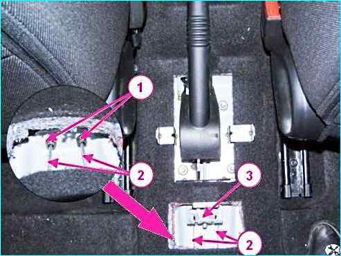
Disconnecting the drive cables from the hand brake lever: 1 - cable lining end; 2 - hand brake cable; 3 - cable equalizer
Using a 10 mm wrench, loosen the adjusting nut 2, Fig. 1, of the hand brake lever and disconnect both cables 2, Fig. 3, from the equalizer 3.
Using pliers and a screwdriver, remove the tips 1, Fig. 3, of the cable sheaths 2 from the holes in the floor tunnel.
Remove the rear wheels.
Using a 24 mm head, unscrew the three nuts 1, Fig. 4, of the fastenings and remove the protective screen 2 of the body floor.
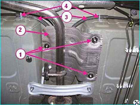
Disconnecting the cables from the body: 1 - nuts securing the protective screen of the body floor; 2 - protective screen of the body floor; 3 - cable sheaths; 4 - cable sheath fastening brackets
Using a flat-head screwdriver, release the sheaths 3 of the cables from the brackets 4 fastening to the bottom of the car body.
Remove the rear brake pads, as described in the article - "Repairing the rear wheel brakes".
Using a screwdriver and pliers, disconnect the cables from the pad drive levers and remove the tips 1, figure 5, cables 2 from the holes in the brake shields.
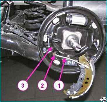
Disconnecting the cables from the brake shield: 1 - cable; 2 - cable tip; 3 - brake shield
Remove the cables from the guide holes in the brackets on the rear suspension arms and in the brackets for attaching the rear suspension arms to the body.
Remove the cables.
Installing the handbrake cables
Install the cables in the guide holes in the brackets for attaching the rear suspension arms to the body and in the brackets on the rear suspension arms.
Install the ends of the cable sheaths in the holes in the brake shields.
Install the ends of the cable sheaths in the holes in the body floor tunnel and secure the cable sheaths in the brackets for attaching to the bottom of the body.
Install the rear brake pads, as described in the previous article.
Install the rear wheels.
Connect the cables to the equalizer of the hand brake lever.
Adjust the hand brake lever as described above.
Install the floor tunnel lining.
Check the efficiency of the working brake system.


