The air conditioning system serves to reduce the temperature and humidity of the air in the car
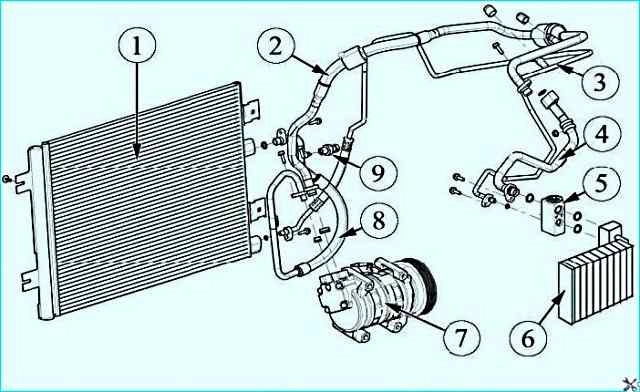
The system consists of the following parts shown in Figure 1: compressor, condenser, evaporator and pipelines.
The air conditioning system is controlled by a control unit and sensors.

Air conditioning system parts: 1 - condenser; 2 - pipeline connecting the compressor to the evaporator; 3 - pipeline connecting the condenser to the evaporator; 4 - pipeline connecting the compressor to the evaporator; 5 - thermostatic expansion valve; 6 - evaporator; 7 - compressor; 8 - pipeline connecting the compressor to the condenser; 9 - pressure sensor
The compressor creates the pressure necessary for the operation of the air conditioning system and ensures the circulation of the refrigerant. The compressor is installed on the engine under the generator.
The torque is transmitted to the compressor shaft from the crankshaft by a poly V-belt through an electromagnetic clutch.
The condenser cools the gaseous refrigerant at high temperature and under high pressure due to heat exchange with the surrounding air, condensing it into a liquid refrigerant.
The condenser is installed on the radiator frame in front of the cooling system radiator.
The evaporator cools and dries the air in the car interior due to heat exchange with the refrigerant.
The evaporator unit is installed in the housing of the ventilation, heating and air conditioning system unit.
The receiver-dryer is designed to accumulate the refrigerant in a liquid state, separating moisture and possible mechanical particles from it.
The receiver-dryer is mounted on condenser.
A removable filter-drier is built into the receiver.
The pipelines connect the elements of the air conditioning system to each other by means of an end connection through a sealing ring with a threaded fixation of this connection.
The thermostatic expansion valve (TEV) is designed to regulate the flow of refrigerant from the condenser to the evaporator, it is installed in front of the evaporator.
The air conditioning system is controlled using the controller of the automatic climate control system (abbreviated - SAUCU), a cabin temperature sensor, a pressure sensor, and an ambient temperature sensor.

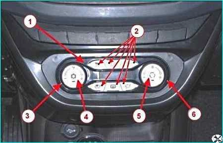
Control unit climate control system: 1 – air conditioning unit; 2 – air flow distribution buttons; 3 – recirculation temperature control handle; 6 – air speed control handle in the passenger compartment; 4 – air conditioner on/off button; 5 - electric fan mode switch button
The automatic climate control system controller is located in the vehicle interior on the instrument panel console.
The ACS controller performs the functions of controlling the air temperature in the vehicle interior, adjusting the air flow distribution, and adjusting the air flow speed.
The purpose of the ACS controller controls is shown in Figure 2.
The cabin air temperature sensor (CATS) monitors the air temperature in the vehicle interior and signals the compressor to turn on/off when the air temperature deviates from the set value.
The pressure sensor is installed on the high-pressure pipeline.
The pressure sensor signals the compressor to turn off/on when the pressure deviates (increases or decreases) from the operating value.
Checking the compressor electromagnetic clutch engagement
Start the engine and warm it up to operating temperature, press the air conditioner on button.
Checking the amount and condition of the refrigerant in the air conditioning system
Check the amount and condition of the refrigerant in the air conditioning system:
- - connect the service hoses to the fittings on the air conditioning system pipes and open the valves on the hose tips;
- - start and warm up the engine to operating temperature;
- - set the air recirculation mode to the outside air intake position;
- - turn on the heater fan motor and set the maximum rotation speed;
- - open the central and side ventilation nozzles on the panel and set them to the neutral position;
- - set the air conditioner switch to the "on" position and set the temperature regulator to the minimum value of the cabin air temperature;
- - close all windows and doors of the car;
- - ensure constant operation of the engine cooling system fan;
- - set the engine crankshaft speed to 1500 rpm;
- - measure the ambient air temperature;
- - wait 5 minutes and measure the air temperature from the side body ventilation nozzles;
- - after the values have stabilized, determine the temperature difference between the outside air and the highest value of the air temperature from the ventilation nozzles;
If the temperature difference between the ambient air temperature and the highest value of the temperature from the ventilation nozzles is less than 5°C, then the system is faulty and it is necessary to diagnose the air conditioning system.
Possible air conditioning system malfunctions, causes and solutions
- Malfunction - Cause, solution
No cooling:
- - The heater fan does not work, the fuse is faulty or blown - replace the fuse
- - The switch on the SAUCU controller (control unit) is faulty - Replace the controller (control unit)
- - The fan speed controller (FSC) is faulty - Replace the controller
- - The electrical wiring is faulty - Check the electrical wiring and fix the fault
- - The fan motor is faulty - Replace the heater fan
- - The SAUCU controller (control unit) is faulty - Replace the controller (control unit)
- - The compressor does not work, the electromagnetic clutch fails - Replace the compressor
- - Lack of refrigerant in the system - Check the amount of refrigerant charged, eliminate leaks, restore the amount of refrigerant
- - The switch on the SAUCU controller (control unit) is faulty - Replace the heater control lever unit
Insufficient cooling (evaporator is covered ice):
- - Heater fan is faulty - Check and, if necessary, replace the fuse or damaged wires and terminals, or the SAUCU controller (control unit), or the RCHV, or the fan
- - Evaporator is dirty - Clean the evaporator
- - TRV is faulty - Replace TRV
- - Receiver-dryer is dirty - Replace the receiver-dryer cartridge
- - Moisture in the system - Unload the refrigerant from the system, replace the receiver-dryer cartridge, dry and fill the system
- - TRV is faulty: - incorrect installation of TRV, TRV is dirty or jammed, its mesh is clogged, there is a leak in the thermal bulb, the TRV valve does not close - Replace TRV
- - Fault refrigerant in the system - Check the amount of refrigerant charged, eliminate leaks, restore the amount of refrigerant
- - Compressor valves are faulty - Replace the compressor
- - Attachment drive belt is slipping - Tighten or replace the attachment drive belt
- - Air and non-condensable gases in the system - Bleed air and non-condensable gases
- - Receiver-dryer is dirty - Replace the receiver-dryer cartridge
- - Heater fan is faulty, heater fan does not turn on - Check and, if necessary, replace the fuse, damaged wires and terminals or controller (control unit), or expansion valve, or fan
- - Condenser is dirty, condenser fan does not work - Clean the condenser or replace the cooling fan
- - Cabin ventilation air filter is dirty - Clean or replace the filter
Increased compressor noise:
- - Insufficient or excess oil in the system - Check the oil level and bring it up to standard
- - Loose compressor mounting elements - Tighten the bolts
- - Worn or broken compressor parts - Replace the compressor
- - Excess refrigerant in the system - Unload the excess refrigerant
- - Low supply voltage of the compressor electromagnetic clutch or it is faulty - Measure the supply voltage, check the reliability of the connections in the electrical wiring. If the coupling is faulty, replace the compressor
High suction pressure:
- - Excess refrigerant in the system - Check the amount of refrigerant charged, discharge the excess
- - High outside air temperature - Normal operating temperature of the system up to +45˚ C
- - Poor evaporator blowing, heater fan is faulty - Check and, if necessary, replace the fuse or damaged wires and terminals, or the controller (control unit), or the expansion valve, or the fan
- - Compressor valves are faulty - Replace the compressor
High discharge pressure:
- - Excess refrigerant in the system - Discharge excess refrigerant
- - Air and non-condensables gases in the system - Release air and non-condensable gases in the system
- - the condenser is dirty, the condenser fan is not working - Clean the condenser, troubleshoot the cooling fan
- - the heater fan is not working - Check and, if necessary, replace the fuse, or controller (control unit), or expansion valve, or fan, or fix wiring fault
Low suction pressure:
- - Lack of refrigerant in the system - Check refrigerant charge, eliminate leaks, restore refrigerant charge
- - Receiver-drier is dirty - Replace receiver-drier cartridge
- - Evaporator is dirty or frozen - Unload refrigerant from the system, replace receiver-drier cartridge, dry and refill the system
Heater fan does not work:
- - Faulty or blown fuse - Replace fuse
- - Faulty switch on the SAUCU controller (control unit) - Replace the controller (control unit)
- - Faulty RCV - Replace RCV
- - Faulty wiring - Check wiring and troubleshoot
- - Faulty fan motor - Replace fan
- - Faulty controller (control unit) - Replace controller (control unit)
High discharge pressure:
- - Excess refrigerant in the system - Check the amount of refrigerant charged, discharge excess
- - Condenser is dirty, condenser fan does not work - Check the operation of the cooling fan, clean the condenser
Low discharge pressure:
- - Lack of refrigerant in the system - Check the amount of refrigerant charged, troubleshoot leaks, restore the amount of refrigerant
- - Low outside air temperature - Normal operating conditions of the system to a temperature of at least + 5˚С
- - Compressor valves are faulty - Replace the compressor


