Removing the air conditioning condenser
Preparing the car for work
Place the car on a lift or inspection pit.
Disconnect the negative battery terminal.
Unload the refrigerant from the car's air conditioning system.
Remove the front bumper in accordance with the article - "Removing and installing bumpers".

Front bumper beam: 1 - beam mounting bolt; 2 - diffuser; 3 - front bumper beam; 4 - ambient temperature sensor
Using a 10 mm socket, unscrew the eight bolts 1, Figure 1, securing the front beam 3 to the body and remove the beam.
Remove the ambient temperature sensor 4 from the hole in the diffuser 2.
Remove the diffuser by disconnecting it from the radiator unit.
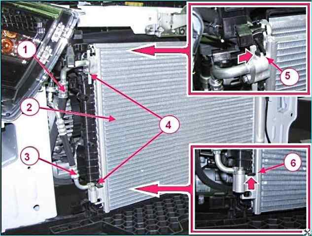
Fastening the condenser and pipelines: 1 - compressor pipeline; 2 - condenser; 3 - evaporator pipeline; 4 - pipeline fastening bolt; 5 - upper condenser retainer; 6 - lower condenser retainer
Using a 10 mm head, unscrew bolts 4, Figure 2, fastening pipelines 1 and 3 to condenser 2, disconnect the pipelines.
Install technological plugs on the pipelines and in the condenser holes.
Press the upper 5 and lower 6 retainers, remove the condenser from the retainers, remove the other side of the condenser from the holders.
Installing the condenser
Install the condenser in the reverse order of removal.
In this case:
- - before connecting the pipelines, add 15 cm3 of compressor oil to the condenser (PAG K-105 or PS – D1 compressor oil, depending on complete set);
- - install new sealing rings on the pipelines, apply compressor oil to the sealing rings.
Tightening torque of the bolts for fastening the pipelines to the condenser is 6-8 Nm (0.6-0.8 kgf.m) (the following is used: - replaceable head 8, ratchet and extension, torque wrench).
Perform vacuuming of the air conditioning system and load the system with refrigerant in accordance with the requirements of the operating instructions for the service equipment (refrigerant R134a or HFO (1234) yf, depending on the complete set, loading rate 390 ± 20 g).
Check the operation of the air conditioning system.
Removing the evaporator unit
Prepare the car for work. Install the car on a lift or inspection pit. Disconnect the negative terminal of the battery.
Unload the refrigerant from the vehicle's air conditioning system.
Drain the coolant.
Remove the ventilation, heating and air conditioning unit.
Unscrew the screws securing the right and left parts of the ventilation, heating and air conditioning unit housing, press the latches and separate the housings (use a Torx 20 socket, ratchet, or flat-head screwdriver).
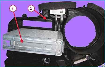
Evaporator: 1 - air conditioning system evaporator; 2 - housing of the ventilation, heating and air conditioning unit
Remove evaporator 1, figure 3, from housing 2 of the ventilation, heating and air conditioning unit.
Check the evaporator elements for mechanical damage to the tubes, plates and threaded connections.
Replace damaged parts or the evaporator unit (visual inspection).
Installing the evaporator unit
Install the evaporator unit in the reverse order of removal.
In this case:
- - before installing the evaporator, add 25 cm 3 of compressor oil to the evaporator (compressor oil PAG K-105 or PS – D1, depending on the configuration);
- - install new sealing rings on the pipelines, apply oil to the sealing rings compressor.
Tightening torque of the bolt securing the pipeline block to the evaporator 6-8 Nm (0.6-0.8 kgf.m) (used: - replaceable head 8, ratchet and extension, torque wrench).
Perform vacuuming of the air conditioning system and load the system with refrigerant in accordance with the requirements of the operating instructions for the service equipment (refrigerant R134a or HFO (1234) yf, depending on the configuration, loading rate 390±20 g).
Check the operation of the air conditioning system.
Removing and installing the compressor
Preparing the car to perform the work. Installing the car on a lift or inspection pit. Disconnect the negative terminal of the battery.
Unload the refrigerant from the vehicle's air conditioning system.
Using a 17 mm socket, unscrew the front right wheel mounting bolts, raise the vehicle to a height convenient for work, and remove the wheel.
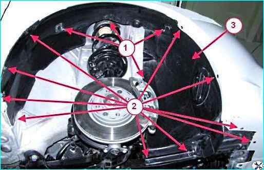
Front fender shield: 1 - front fender shield mounting pin; 2 - front fender shield mounting self-tapping screw; 3 - front fender shield
Using a T20 Torx head, unscrew ten screws 2, Fig. 4, securing the front fender shield 3, remove four pins 1, and remove the shield.
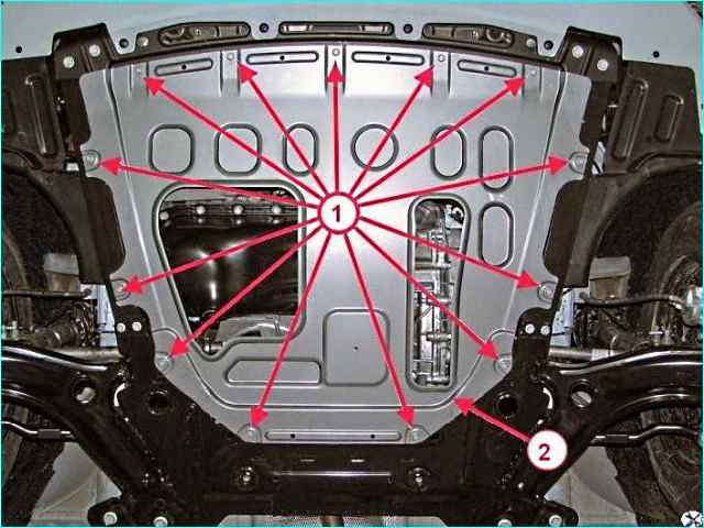
Engine mudguard: 1 - engine mudguard mounting bolt; 2 – engine mudguard
Using a 10 mm socket head, unscrew the thirteen bolts 1, Fig. 5, securing the engine mudguard 2, remove the mudguard.
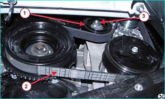
Attachment drive belt 1 – tension roller; 2 – attachment drive belt; 3 – roller fastening nut
Remove the plug of the tension roller 1, Fig. 6, loosen the fastening nut 3 and move the tension roller to the upper position (used: - replaceable head 13, Torx T55, ratchet).
Remove the belt from the compressor pulley.
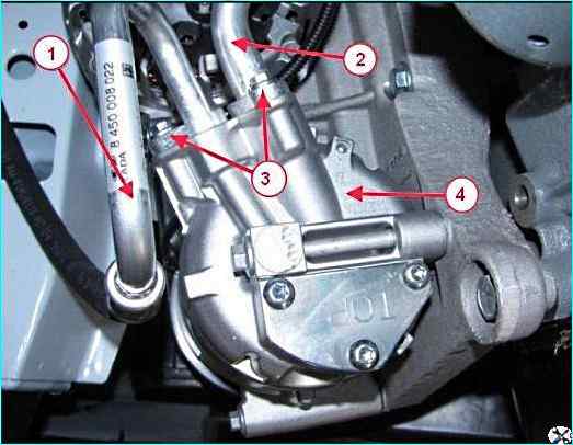
Disconnecting the pipelines from the compressor: 1 - high-pressure compressor pipeline; 2 - low-pressure compressor pipeline; 3 – pipeline fastening bolt; 4 - compressor
Using an 8 mm head, unscrew bolts 3, Figure 7, fastening the high 1 and low 2 pressure pipelines to the compressor 4, disconnect the pipelines from the compressor.
Install technological plugs on the pipelines and in the compressor openings.
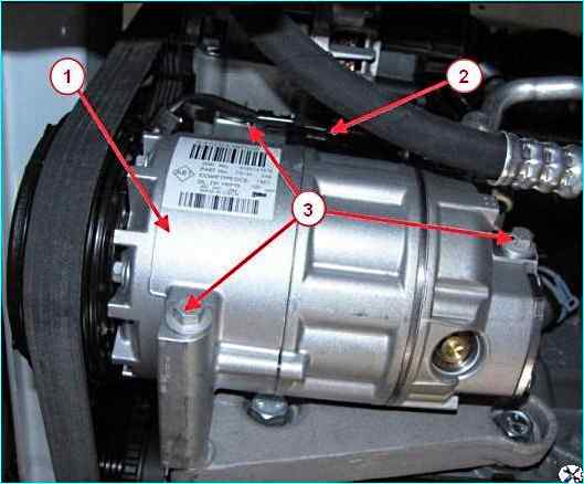
Compressor fastening: 1 - compressor; 2 - wiring harness block; 3 - compressor mounting bolt
Disconnect block 2, figure 8, of the wiring harness from the electromagnetic clutch of compressor 1.
Using a 10 mm head, unscrew the bolts 3 of the compressor mounting, remove the compressor.
Installing the air conditioning compressor
Install the compressor in the reverse order of removal.
In this case:
- before connecting the pipelines, install new sealing rings on the pipelines, apply compressor oil to the sealing rings.
Tightening torque of the bolt securing the pipeline block to the evaporator 6-8 Nm (0.6-0.8 kgf.m) (used: - replaceable head 8, ratchet and extension, torque wrench).
Install the drive belt of the attachment units on compressor pulley.
Tension the drive belt of the mounted units, for this:
- move the tension roller to the lower position in a clockwise direction and tighten the tension roller fastening nut. Tightening torque of the nut 30-36 Nm (3.0-3.6 kgf.m).
Perform vacuuming of the air conditioning system and load the system with refrigerant in accordance with the requirements of the operating instructions for the service equipment (refrigerant R134a or HFO (1234) yf, depending on the configuration, loading rate 390±20 g).
Check the operation of the air conditioning system.
Removal and installation of air conditioning pipelines
Dismantling the unit from the pipelines or compressor hoses is carried out after complete unloading of the refrigerant.
Fixing of pipelines and hoses with any of the elements of the air conditioning system is carried out by a threaded connection.
To disconnect a pipeline or hose, unscrew the bolt (nut) securing the connection, disconnect the parts, install technological plugs on the open parts main line.
To ensure free access to the connection, remove the parts that impede free access.
Pipe block:
- Remove the engine splash guard, see Figure 5.
- Using an 8 mm head, disconnect the high-pressure line from the condenser.
- Using an 8 mm head, disconnect the low-pressure line from the compressor suction hose.
- Using an 8 mm head, unscrew the bolt securing the pipeline clamping plate to the evaporator.
- Using a 10 mm head, disconnect the attachment points of the pipeline block to the body, remove the pipeline block.
Suction compressor hose:
- Remove the engine mudguard, see Figure 5.
- Using an 8 mm head, disconnect the suction hose from the compressor.
- Using an 8 mm head, disconnect the suction hose from the low-pressure line, remove the hose.
Discharge compressor hose:
- Remove the engine mudguard, see Figure 5.
- Remove the front bumper.
- Using an 8 mm head, disconnect the discharge hose from the compressor.
- Using an 8 mm head, disconnect the discharge hose from the condenser, remove hose.
Installation
Install the pipeline and hose unit in the reverse order of removal.
In this case:
- - before installation, add 20 cm 3 of compressor oil to the evaporator or compressor (PAG K-105 or PS – D1 compressor oil, depending on the configuration);
- - install new sealing rings, apply compressor oil to the sealing rings;
- - tightening torque of the bolt securing the pressure plate of the pipeline unit to the evaporator 6-8 Nm (0.6-0.8 kgf.m);
- - tightening torque of the nut securing the low-pressure pipeline and suction hose 6-8 Nm (0.6-0.8 kgf.m);
- - tightening torque of the pipeline fastening bolt high pressure to the condenser 6-8 Nm (0.6-0.8 kgf.m);
- - tightening torque of the compressor hose fastening bolts to the compressor 6-8 Nm (0.6-0.8 kgf.m).
Perform vacuuming of the air conditioning system and load the system with refrigerant in accordance with the requirements of the operating instructions for the service equipment (refrigerant R134a or HFO (1234) yf, depending on the configuration, loading rate 390±20 g).
Check the operation of the air conditioning system.


