Remove the supports if they are worn out or when dismantling the powertrain units
Removing and installing the left support
Prepare the car for work. Install the car on a lift or in an inspection pit.
Disconnect the negative terminal of the battery.
Remove the resonator and air filter.
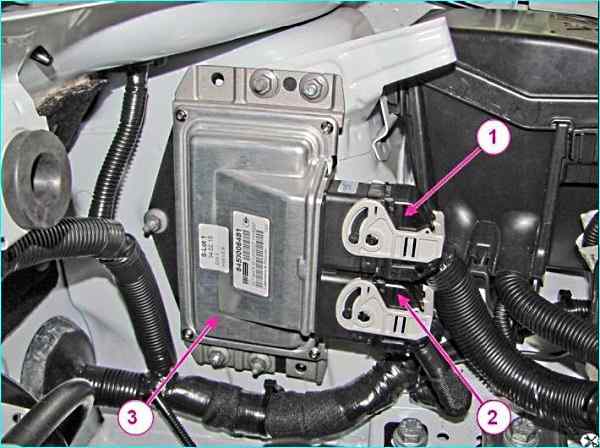
ECM controller: 1 - ignition system wiring harness connector; 2 - front wiring harness connector; 3 - ECM controller
Disconnect the connectors of the ignition system wiring harness 1, Figure 1, and the front wiring harness 2 from the ECM controller 3 and move the harnesses to the side.
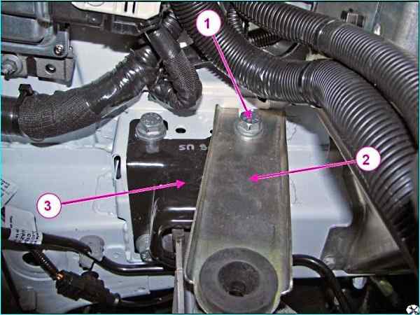
Air filter bracket: 1 - bolt; 2 - air filter bracket; 3 - left support of the power unit suspension
Using a 16 mm head with an extension, loosen bolt 1, Figure 2, fastening bracket 2 of the air filter and remove the bracket from the left support 3 of the power unit suspension.
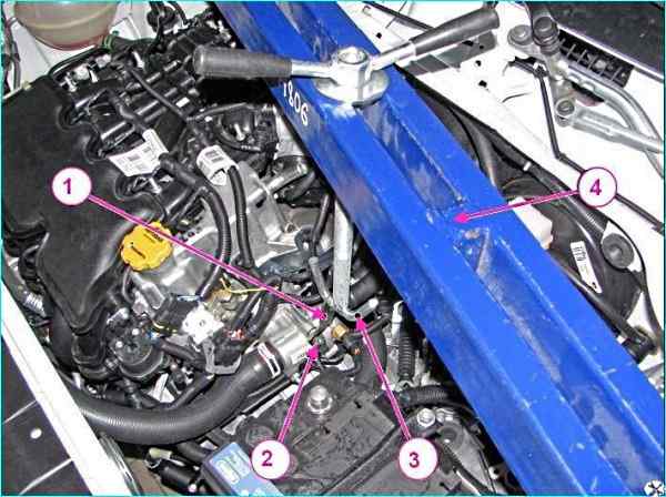
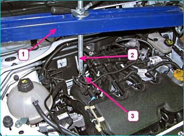
Hanging the power unit: 1 - technological eye; 2 - nut; 3 - crossbar hook; 4 - crossmember for hanging the power unit
Install the technological eye 1, figure 3, on the upper stud of the thermostat mount and secure it with nut 2.
Install the crossmember 4 on the vehicle for hanging the power unit, insert the hook 3 of the crossmember into the eye of the technological eye on the left side of the engine and hang the power unit.
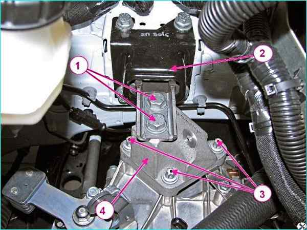
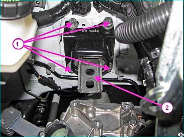
Fastening the left support of the power unit suspension to the gearbox: 1 - power unit mounting bolt unit to the left support; 2 left support of the power unit suspension; 3 - bolt for fastening the bracket to the gearbox; 4 - bracket
Using an 18 mm head, unscrew and remove two bolts 1, Figure 4, securing the power unit to the left support 2.
Using a Torx E12 head, unscrew three bolts 3 securing bracket 4 of the left support to the gearbox and remove the bracket.
Fastening the left support of the power unit suspension to the body: 1 - bolt securing the left support of the power unit suspension to the body; 2 - left support of the power unit suspension
Using a 16 mm head, unscrew the four bolts 1, Fig. 5, securing the left support 2 of the power unit suspension to the body and remove the left support
Installation
Install the left support 2, Fig. 5, of the power unit suspension on the car body and secure it with bolts 1.
Do not tighten the air filter bracket mounting bolt completely.
Tightening torque of the three bolts securing the left support of the power unit suspension to the body is 53÷71 Nm (5.3÷7.1 kgf.m).
Install bracket 4, Fig. 4, of the left support of the power unit suspension on the gearbox and secure it with bolts 3.
Tightening torque bolts 53÷71 Nm (5.3÷7.1 kgf.m) (TorxE12 replaceable head, extension, ratchet).
Install two bolts 1 for fastening the power unit to the left support 2 of the power unit suspension.
The tightening torque of the bolts is 90…120 Nm (9÷12 kgf.m).
Install and push the bracket 2, Fig. 2, of the air filter into the body until it stops.
The tightening torque of bolt 1 for fastening the left support of the power unit suspension to the body is 53÷71 Nm (5.3÷7.1 kgf.m).
Remove hook 3, Fig. 3, of crossbar 4 for hanging the power unit from the eye of the technological eye 1 and remove the crossbar from car.
Unscrew nut 2 and remove the technological eye from the upper thermostat mounting stud.
Connect connectors 1 and 2, Figure 1, of the wire harness to controller 3.
Install the resonator and air filter.
Connect the ground wire terminal to the battery
Removing and installing the right support of the powertrain suspension
Prepare the car for work. Install the car on a lift or in an inspection pit.
Disconnect the negative terminal of the battery.
Hanging out the power unit: 1 - crossbar for hanging out the power unit; 2 - crossbar hook; 3 - engine eye
Install crossmember 1, Figure 6, on the vehicle to hang the power unit, insert hook 2 of the crossmember into eye 3 of the right eye, and hang the power unit on the right side.
For vehicles with engines 11189 and 21129
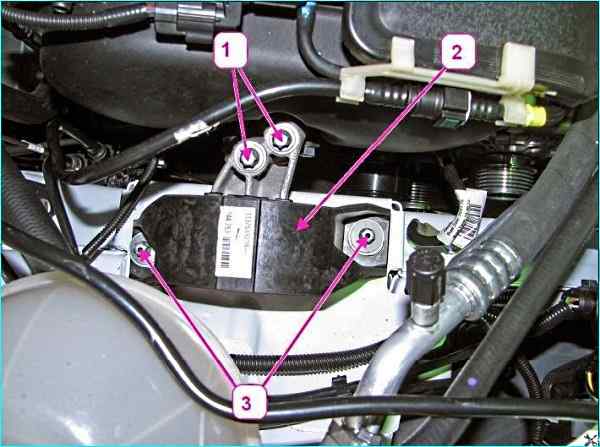
Right support of the power unit suspension: 1 - bolt for fastening the power unit to the right support; 2 - right support of the power unit suspension; 3 - bolt securing the right support of the engine mount to the body
Using a TorxE12 head, loosen and remove the two bolts 1, Figure 7, securing the engine to the right support 2 of the engine mount.
Mark the position of the right engine mount on the body with a marker.
Using a TorxE12 head, loosen and remove the two bolts 3 securing the right support of the engine mount to the body and remove the right support.
For vehicles with an HR16 engine:
Right support of the power unit suspension HR16: 1 - fuel pipe; 2 - pipe of the gasoline vapor recovery system; 3 - bolt of fastening of the bracket of the right support of the suspension to the engine; 4 - bolt of fastening of the right support of the suspension of the power unit to the body; 5 – right support of the power unit suspension
Disconnect the fuel pipe 1, Fig. 8, and the pipe 2 of the gasoline vapor recovery system from the holders.
Mark the position of the right support of the power unit suspension on the body with a marker.
Using a 16 mm head with an extension, unscrew the bolts 3 securing the bracket of the right suspension support to the engine.
Using a 16 mm head, unscrew the bolts 4 securing the right support of the power unit suspension to the body and remove the right support 5.
Installation
For cars with engines 11189 and 21129:
Install the right support 2, Fig. 7, of the power unit suspension on the body unit.
Install, without tightening, two bolts 1 securing the right support of the power unit suspension to the bracket of the power unit suspension (replaceable Torx E12 head, extension, ratchet).
Install, without tightening, two bolts 3 securing the right support of the power unit suspension to the body.
Tighten the two bolts securing the right support of the power unit suspension to the bracket
of the power unit suspension with a torque of 53÷71 Nm (5.3-7.1 kgf.m).
Install the right support of the power unit suspension according to the marks on the body made during its removal, and tighten the two bolts securing the right support of the power unit suspension to the body with a torque of 53-71 Nm (5.3-7.1 kgf.m).
For vehicles with HR16 engine:
Install the right support 5, Figure 8, of the powertrain suspension according to the marks on the body made during its removal, and secure with bolts 3 and 4 securing the right suspension support to the engine and body.
Tighten to the required torque:
- - bolts securing the bracket of the right suspension support to the engine 53-71 Nm (5.3-7.1 kgf.m);
- - bolts securing the right suspension support to the body 53-71 Nm (5.3-7.1 kgf.m).
Install the fuel pipe 1 and pipe 2 of the gasoline vapor recovery system in the holders.
Operations for all vehicle configurations:
Remove hook 2, Figure 6, crossbars for hanging the power unit from the eye of the right eye 3 on the engine and remove crossbar 1 from the car.
Connect the terminal of the ground wire to the battery.
Removing and installing the rear support of the power unit
Prepare the car for work. Place the car on a lift or in an inspection pit.
Disconnect the negative battery terminal.
Remove the engine protection.
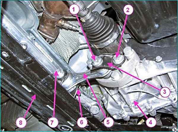
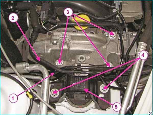
Rear support of the power unit suspension: 1 - bolt for fastening the rod of the rear suspension of the power unit; 2 - bolt for fastening the bracket; 3 - bracket; 4 - gearbox; 5 - rod of the rear suspension of the power unit; 6 - nut; 7 - bolt for fastening the rod of the rear support of the suspension of the power unit to the subframe; 8 - front suspension subframe
Using a 18 mm head, unscrew bolts 1 and 2, Figure 9, securing bracket 3 and rod 5 to gearbox 4 and remove bracket 3.
Unscrew nut 6 of bolt 7 securing rod 5 of the rear support of the powertrain suspension to subframe 8 and remove the rod.
Installation
Install rod 5, Figure 9, of the rear support suspension of the power unit to the subframe 8, secure with bolt 7 and screw on nut 6 without tightening it completely.
Install bracket 3 and tighten bolts 1 and 2 for fastening bracket 3 and rod 5 to gearbox 4.
Tighten to the required torque:
- - bolt 1 for fastening rod 5 of the rear support of the suspension of the power unit to the gearbox 90-120 Nm (9-12 kgf.m);
- - bolt 2 for fastening bracket 3 to the gearbox 90-120 Nm (9-12 kgf.m);
- - nut 6 of bolt 7 for fastening rod 5 of the rear support of the suspension of the power unit to subframe 6 of the front suspension 90-120 Nm (9-12 kgf.m).
Install the engine mudguard.
")

")
")
")
")
")
")
")