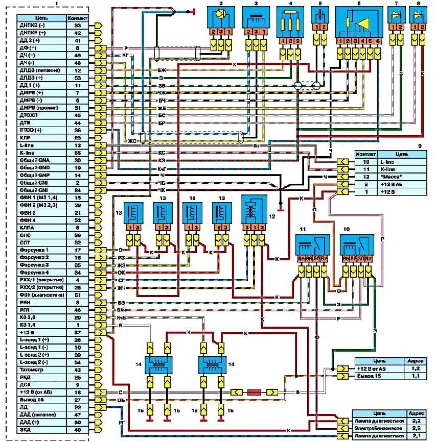
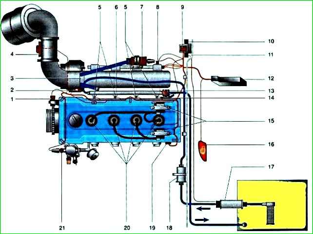
The ZMZ-406 engine is equipped with a microprocessor ignition system, which consists of a control unit for fuel injection and ignition systems, two ignition coils of types 30.3705 or 301.3705, spark plugs, high-voltage and low-voltage wires
The control unit is installed in the car interior on the right side under the instrument panel, behind the body side trim.
The ignition coils are installed on the cylinder head cover.
The control unit receives signals from sensors installed on the engine and, based on this, adjusts the ignition timing, which allows for optimal power, economic and toxicity indicators.
ZMZ-406 microprocessor engine control system:
- - controls the power supply to the fuel pump;
- - controls the supply of gasoline to the intake pipe of each cylinder in accordance with the engine operating cycles;
- - provides a spark on the candles and adjusts the ignition timing, ensuring knock-free operation of the engine;
- - controls the air supply at the time of start-up.
The system consists of an electronic control unit, a set of sensors, actuators and connecting wires with connectors.
An electronic control unit is a specialized computer that receives signals from sensors and controls the actuators of the system.
The microprocessor of the control unit, according to the program entered into the unit’s memory and based on data received from the sensors, calculates the necessary signal parameters for the actuators.
The matching elements of the control unit transmit these signals to the system actuators.
Control system sensors: synchronization, camshaft position, detonation, air flow, throttle position, coolant temperature and air in the intake manifold.
Actuators: electromagnetic injectors, ignition coils, secondary air regulator, warning lamp, electric fuel pump relay and unloading relay.
If the throttle position sensor, mass air flow sensor or knock sensor fails, the system switches to a backup mode, which allows you to get to the repair site.
The system informs the driver about the transition to the backup mode by turning on the KMSUD indicator lamp on the instrument panel.
Operating the engine in this mode does not have a negative effect on its condition, but starting is difficult, throttle response deteriorates, fuel consumption and exhaust gas toxicity increase.
Electronic engine control unit
Information about control system settings and faults is stored in the unit’s memory and can be read through the diagnostic connector.
When the battery is disconnected, information about faults is erased. This has no effect on engine performance in the future, but may lead to temporary deterioration of the engine operational properties.
The MIKAS 5.4 control unit is based on the SAB80C517A microprocessor from SIEMENS.
The software is stored in a read-only memory (ROM) with a capacity of 32 KB and a random access memory (03U).
Cars with a ZMZ-4062 engine produced before May 1997 were equipped with MIKAS 5.4 201.3763.001 control units, in which the ROM 201.001 chip was installed.
Since August 1998, cars have been equipped with MIKAS 5.4 201.3763.003 units, in which a ROM 201.003 chip is installed that controls the electric fan and air conditioning compressor.
The control unit diagnoses circuits of sensors and actuators, and also checks the serviceability of its own circuit.
When a malfunction is detected, the unit turns on the KMSUL indicator lamp.
The control unit diagnostic system has several operating modes.
Operating mode
When the ignition is turned on, the electronic control unit constantly monitors most incoming and outgoing signals.
The unit informs about faults that appear and disappear by briefly (about 0.5 s) turning on the indicator lamp. In this case, fault codes that appear more than once every two minutes are stored in the memory of the electronic unit.
Fault codes that do not appear within two hours will be erased from memory.
A fault that is constantly present in the system is indicated by a constantly burning indicator lamp.
Diagnostic information output mode
In this mode, the electronic unit, using a warning lamp, displays fault codes recorded and stored in memory.
Each fault has a two- or three-digit light code. Each digit of the code corresponds to a series of short (0.5 s) flashes of the lamp. There is a pause between the series (about 1.5 s).
After all the digits of one code have been transmitted (2 or 3 series of flashes, depending on whether the code is two or three digits), a long pause (about 4 s) follows.
For example: a fault with code “131” will be transmitted in the following sequence: one short on, short pause, three short on, short pause, one short on, long pause.
Each fault code is repeated three times.
Mode of operation with diagnostic equipment
For a more complete check of the engine management system, a special tester 08T-2 is connected to the diagnostic connector.
Such work can only be carried out by specialists who have the necessary equipment.
Default code clearing mode
Fault codes are erased from memory when the battery is disconnected.