The heating system is designed for continuous operation for a long time and provides multiple exchanges of air in the cabin, the required air speed and temperature, and the temperature of the cabin surfaces
The cabin is heated by air heated in the heater radiator 19.
Outside air passes through the grille between the windshield and the hood, changes direction and is separated from rainwater.
Then the air from the air intake box 10 enters the heater casing and, depending on the location of the mixing dampers, enters either through the heater radiator or directly into the air flow distributors left 5 and right 9.
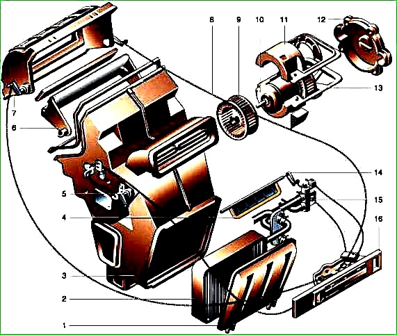
Parts of the main heater for cars manufactured since 2003: 1 - bracket; 2.4 - damper axis levers; 3 - bracket for fastening the drive rod shells; 5 - clamp; 6, 7,18 - drive rod shells; 8,9 - damper drive racks; 10 - protective casing; 11 - heater housing; 12 - fan cover; 13 - wire seal; 1 4 - wire; 15 - fan cover fastening screw; 16 - heater fan; 17 - fan impeller seal; 19 - heater radiator; 20 - radiator cap gasket; 21 - radiator cap; 22 - heater valve; 23 - connecting hose; 24 - cover fastening screw
The heating and ventilation unit (HVU) consists of a heater body 11, including a casing 4 and a casing cover 1, connected through a gasket 6 by brackets 7, left air flow distributors 5 and right 9, attached to the casing and the heater casing cover with screws 8, radiator 19, radiator cap 21, electric fan 16, fan cover 12, dampers for mixing outside air, dampers for distributing air flows and ventilation dampers located inside the OVU housing and controlled by rails 8 and 9 of the protective casing 10, which prevents damage to the rails during installation.< /p>
An additional resistor 8 is installed on the cover of the OVU casing, providing three rotation speeds of the electric fan.
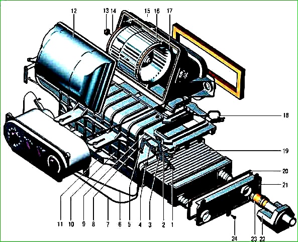
The main heater for cars manufactured before 2003: 1 - radiator trim; 2 - heater radiator; 3 - heater casing; 4 - lower damper; 5 - axis of the central air damper; 6 - air intake duct damper; 7 - air intake box; 8 - air damper drive rod; 9 - fan; 10 - electric motor; 11 - upper cover of the electric motor; 12 - electric motor cover; 13 - lower cover of the electric motor; 14 - lower damper lever; 15 - heater tap; 16 - heater control panel
The heater is mounted on the bracket through rubber bushings 11 with two bolts 9 to the wall of the engine compartment and bolt 3 through the rubber bushing to the cross member 19 of the OVU mounting bracket.
The heater valve is driven by a microelectric motor through a mechanical gearbox; the tap has two positions - completely open or completely closed.
The OVU radiator is connected by hose 23 to the heater control valve and to the engine cooling system by hoses 15 and 17.
The hoses are connected to the hoses of the engine compartment through a clip 14, attached to the compartment wall with two nuts 16.
A tee 12 is installed in the heater hose system to eliminate air pockets in the OVU pipeline system when filling (replacing) coolant in the engine cooling system.
The OVU is connected to the air distribution channels made in the instrument panel through air ducts 6 and 7
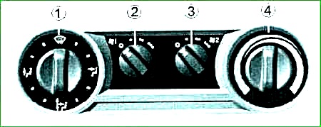
The OVU is controlled by regulators 1, 2, 3 and 4, located on the heating and ventilation control panel.
3 - plug (for GAZ-2705) or knob for adjusting the intensity of air heating in the GAZ-2705 “Combi” cabin or in the bus interior 4 - the handle for adjusting the air temperature in the cabin (the handle simultaneously controls the heater valve and the mixing valves).
The leftmost position of the knob (the wide part of the blue symbol) corresponds to the ventilation mode.
In this position of the handle, the heater valve is closed, and the mixing valves, controlled by rod 18, completely shut off the heater outside air is allowed to enter the heater radiator and the ventilation channel is completely open.
The intermediate and extreme right positions of knob 4 (the wide part of the red symbol) correspond to the heating mode.
In this mode, when the handle is turned 9° clockwise, the tap is open, the mixing dampers partially open the channel for the supply of outside air to the heater radiator and partially block the ventilation channel (intermediate switching on of the heating system).
When the handle is in the extreme right (clockwise) position, the ventilation channel is completely blocked and the entire flow of outside air goes through the heater radiator.
To heat the cabin, open the heater tap, turn knob 4 clockwise to an angle of at least 9° and further turn knob 4 to select a comfortable air temperature.
Removing frost and condensation
To quickly remove frost and condensation from the windshield and side windows you need to:
- - set the air distribution regulator 1 to position
- - set the air temperature regulator 4 to the extreme right position (the wide part of the red symbol);
- - set air quantity regulator 2 to maximum fan performance.
To obtain a comfortable climate, you must:
- - set the air flow distribution regulator 1 to the position you choose;
- - use temperature controller 4 to set the desired air temperature (temperature of outside air or thermal air from the heater);
- - turn the air quantity regulator 2 from position 0 to one of three positions to obtain the desired air flow rate into the cabin.
The central and side ventilation grilles on the instrument panel have knobs (levers) for controlling the dampers, by moving which you can change the direction of air flow, increase or decrease the amount of incoming air until the air inlet channel is completely closed.
To quickly remove fogging and frost from the windows, set knob 1 to the position directing the air flow to the windshield and side windows, knob 4 to the far right position (the wide part of the red symbol), and knob 2 to the far right (clockwise) position maximum rotation speed of the OVU electric fan.
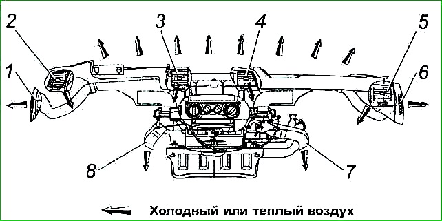
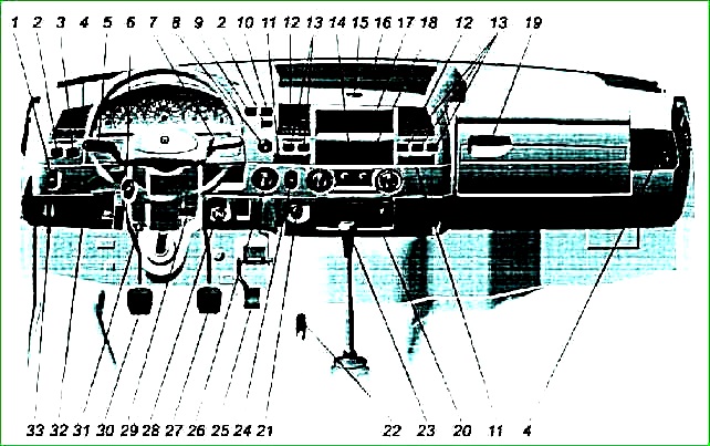
Distribution of air flows in the cabin is carried out through air ducts and pipes 1 2, 3, 4, 5 and 6.
The side 2 and 5 and central air pipes 3 and 4 for the driver and passenger have damper control levers.
By moving them, you can change the direction of air flows, increase or decrease the amount of incoming air, up to completely closing the air supply channel.
The efficiency of the heating system depends on the temperature of the coolant in the engine, which in the cold season must be maintained within 85-100° C.
The ventilation system is designed to create a normal microclimate in the cabin when operating the vehicle in the summer.
The cabin is equipped with supply and exhaust ventilation systems.
Forced supply ventilation is carried out through the OVU with the windows closed, the roof hatch (if equipped) and the heater tap closed
To turn on the ventilation, you need to move knob 4 to the extreme left position (the wide part of the blue symbol) and turn knob 2 to set the required air flow rate into the cabin.
The extreme right position of knob 2 corresponds to the maximum rotation speed of the electric fan.
Select, by turning knob 1, the distribution of air flows in the cabin.
Use the control levers for the pipe flaps to set the most comfortable air direction.
Forced forced ventilation should be used in hot weather at low vehicle speeds and in parking lots.
At vehicle speeds above 50 km/h, supply ventilation can be carried out with the electric fan turned off due to high-speed air pressure.
Supply ventilation is also provided through sliding door windows.
Exhaust ventilation is carried out through slots connected to the atmosphere and located in the lower part of the cabin doors.
Checking the technical condition and maintenance of the heating and ventilation unit (HVU)
Maintenance of the OVU comes down to periodic checking of the technical condition of the heater radiator, valve and hoses of the system, operation of the electric fan, OVU dampers and pipes on the instrument panel that distribute and direct the flow of air supplied to the cabin.
If engine coolant leaks into the cabin, you must first check Check the reliability of fastening the heating system hoses with clamps, the tightness of the radiator and heater tap.
If a leak is detected at the joints, it is necessary to tighten the clamps 13.
If the cause of the leak is the heater radiator (fluid is leaking from the OVU housing), the radiator must be removed, the location of the fluid leak identified and the leak eliminated.
Heater radiator 19 of prefabricated structure, tubular-plate with plastic tanks.
The radiator core is made of aluminum tubes and aluminum cooling plates.
A metal bottom with a rubber gasket is installed on both sides of the core.
The gasket seals the ends of the tubes, and the tank installed on this gasket is pressed against the gasket with bending tendrils.
Screw plastic turbulators are installed inside the tubes for greater heat removal from the heater radiator.
If a leak is found in the place where the tubes are sealed with a rubber gasket, fix it by pressing the bending tendrils of the bottom of the tank.
To do this, you need to securely install the radiator on a rubber mat and lightly press the metal bottom at the place of leakage.
If liquid leaks through damaged tubes, the radiator should be replaced with a new one.
In case of repairs, it is necessary to remove the tanks by bending the antennae of the bottom of the tank, and install repair tubes of a smaller diameter, followed by their burnishing (i.e., increasing the internal diameter of the tubes).
If the tightness of valve 22 is broken, it must be removed and inspected.
If a leak is detected at the connection between the cover and the body, tighten the screws securing the cover or unscrew the screws and replace the gasket.
To check the functionality of the faucet, you need to place your finger on the faucet body and turn handle 4 9-10° from the extreme left position clockwise.
In this case, power is supplied to the electric drive of the faucet and a click should be heard when the locking valve is activated.
If there is no click, the electric drive is faulty.
The tap needs to be replaced.
The OVU electric fan does not work - or it works with increased noise:
The reason for electric fan 16 stopping may be a failure of the fan power supply, jamming of the fan rotor in the heater housing, jamming of the electric motor shaft in the bearings, or unreliable contact in the electrical wire connector 14.
To eliminate jamming of the fan rotor, you need to remove the electric fan, make sure that the two mounting brackets for the electric fan flange 17 are in place and are not jamming the electric fan rotor.
It is necessary to turn the rotor and make sure that the motor shaft rotates freely.
If rotation is difficult or the rotor does not rotate at all, replace the electric fan.
If, when you turn knob 2 to turn on the fan, the air flow speed does not change, you need to check the reliability of the connection of resistance 8 (terminals) to the wiring harness or replace the resistance.
Disassembly and repair of heating and ventilation systems
To remove the heater core:
- - drain the coolant from the engine cooling system (3-4 l);
- - loosen the clamps securing hoses 15 and 17 to radiator fittings 19;
- - disconnect the hoses:
- - unscrew the three screws 24 securing the radiator cover and remove the cover 21 with gasket 20;
- - remove heater radiator 19 from housing 11.
Installation of the heater radiator is carried out in the reverse order.
To remove valve 22 of the electric heater, it is necessary to loosen the hose clamps securing the hoses to the heater valve, disconnect the hoses and remove the valve, having first disconnected the power harness.
Installation of the tap is carried out in reverse order.
To remove the electric fan, you need to open the glove box cover on the instrument panel.
Unscrew the four screws securing the glove box and remove it together with the cover from the instrument panel socket.
Then unscrew the two screws 15 securing the electric fan cover and remove it from the heater body.
Disconnect the electric motor connection wire 14 (disconnect the wiring block), remove the electrical wire seal 13 and remove the electric fan from the heater housing. Installation of the electric fan is carried out in reverse order.
To remove the control panel, you must remove the instrument panel.
Impaired distribution of air flows from the air handling unit
One of the reasons for the violation of the distribution of air flows is the weakening of the brackets 1 securing the shells 6 and 7 of the drive cable rods to the bracket 3.
As a result, when handle 1 is turned, the rod itself bends and the damper does not work.
The bracket(s) must be securely fixed in the holes of the bracket, and if they break, replace them.
Another reason for poor air distribution is the incorrect position of the dampers in air distributors 5 and 9.
To eliminate this drawback, it is necessary: put handle 1 in the position for blowing the windshield and side windows, while the lever 2 of the damper axle should be in the extreme right position, and lever 4 should be in the extreme left position (clockwise).
If this does not happen, then it is necessary to release the rack(s) 8 and 9 from the lock 5, place the lever(s) in the positions indicated above and fix the racks in the latches again.