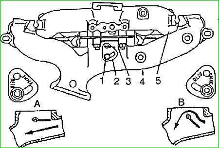
The intake pipe is made of aluminum alloy, the exhaust manifold adjacent to the cylinder head is machined as an assembly with a non-flatness of 0.2 mm, so disassembling the unit unnecessarily is undesirable
The middle part of the intake pipe is heated by exhaust gases passing through the exhaust manifold
The degree of heating can be adjusted manually using the rotating damper 3, depending on the season.
When sector 2 is rotated to a position in which the mark ((winter)) is located against the locking pin, the mixture is heated to the greatest extent; when turning to the summer mark position, heating is the smallest.
The camshaft is cast iron, cast with a steel gear that drives the oil pump and the ignition distributor; has five support journals of different diameters (for ease of assembly):
- first - 52 mm, second - 51 mm, third - 50 mg, fourth - 49 mm, fifth - 48 mm.
The journals rest directly on the surface of the bores in the aluminum cylinder block.
The working surface of the cams and the eccentric of the fuel pump drive is whitened to high hardness when casting the camshaft.
The gear teeth of the oil pump drive are hardened.
The intake and exhaust cam profiles are the same.
The width of the cams is ground to a cone.
The conical surface of the cam, in combination with the spherical end of the pusher, imparts a rotational movement to the pusher when the engine is running.
As a result, the wear of the pusher guide and its end becomes uniform and small.
The intake pipe and exhaust manifold of the 1st and 4th cylinders are connected to each other into one unit through a gasket with four bolts.
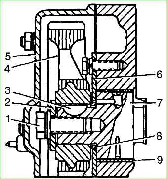
Camshaft 7 is driven into rotation from the crankshaft by helical gear 4. On the crankshaft there is a steel gear with 28 teeth, and on the camshaft there is a textolite gear with 56 teeth.
The use of textolite ensures quiet operation of the gears.
Both gears have two holes with M8x1 25 threads for a puller.
The camshaft rotates 2 times slower than the crankshaft.
The camshaft is held against axial movements by a thrust steel flange 6, which is located between the end of the shaft journal and the gear hub with a gap of 01–0.2 mm.
Axial clearance is provided by spacer ring 8, clamped between the gear and the shaft journal. To improve running-in, the surfaces of the thrust flange are phosphated.
The gear is secured to the camshaft using washer 2 and bolt 1 with M12x1.25 thread. The bolt is screwed into the end of the shaft.
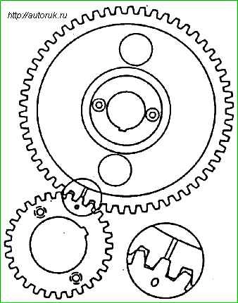
On the crankshaft gear, a mark is applied against one of the teeth, and a mark or drilling is applied against the corresponding cavity of the camshaft gear.
When installing the camshaft, these marks must be aligned.
The camshaft provides the following valve timing phases: the intake valve opens 12° ahead of time before the piston reaches TDC, closes with a delay of 60° after the piston reaches BDC, the exhaust valve opens 54° ahead before the piston reaches BDC and closes with a delay of 18° after the piston reaches TDC.
The specified valve timings are valid with a gap between the rocker arm and the valve of 0.5 mm.
Valve rocker arms 8 are the same for all valves, steel, cast
A bushing made of sheet tin bronze is pressed into the hole in the rocker hub.
A groove is made on the inner surface of the bushing to distribute oil evenly over the entire surface and to supply it to the hole in the short arm of the rocker.
The long arm of the rocker ends with a hardened cylindrical surface resting on the end of valve 2, and the short arm ends with a threaded hole Suitable for adjusting screw.
Adjusting screw 9 has a hexagonal head with a spherical recess for a rod, and at the upper end there is a slot for a screwdriver.
The spherical recess is connected by drilled channels with a groove on the threaded part of the screw.
The groove on the screw is located opposite the hole in the rocker arm, i.e., approximately in the middle of the height of the threaded boss of the short rocker arm.
In this case, the oil passes freely from the rocker channel into the screw channel.
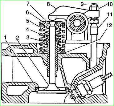
The adjusting screw is locked with locknut 10.
Rocker arms - mounted on a hollow steel axle, which is secured to the cylinder head using four main ductile iron struts, two additional ductile iron struts and pins passed through the struts.
The fourth main strut on the plane adjacent to the cylinder head has a groove through which oil is supplied from the channel in the head into the cavity of the rocker arm axis.
The remaining racks do not have a milled groove, so they cannot be installed in place of the fourth rack.
The rocker arms are kept from axial movement by spacer springs that press the rocker arms to the racks.
The outer rocker arms are located between the additional and main struts; to increase wear resistance, the outer surface of the axle under the rocker arms is hardened.
Under each rocker arm there is a hole for lubrication in the axle.
The valves are made of heat-resistant steel: the inlet valve is made of chromium-silicon steel, the exhaust valve is made of chromium-nickel-manganese with a nitrogen additive.
A more heat-resistant chromium-nickel alloy is additionally fused onto the working chamfer of the exhaust valve. valve stem diameter - 9 mm.
The intake valve plate has a diameter of 47 mm, and the exhaust valve has a diameter of 39 mm.
The operating chamfer angle of both valves is 45°.
At the end of the valve stem there is a recess for the valve spring plate crackers.
Valve spring plates 6 and blockers 7 are made of steel and subjected to surface hardening.
Two springs are installed on each valve: outer 4 with variable pitch with left winding and inner 5 with right winding.
The springs are made of heat-treated high-strength wire and shot blasted.
Steel washers 12 are installed under the springs.
The outer spring is installed downward with the end having a smaller pitch of turns.
The valves operate in metal-ceramic guide bushings.
The bushings are made by pressing followed by sintering from a mixture of iron, copper and graphite powders with the addition of molybdenum disulfide to increase wear resistance.
The inner hole of the bushings is finally processed after they are pressed into the head.
The intake valve bushing is equipped with a retaining ring that prevents spontaneous movement of the bushing in the head.
To reduce the amount of oil penetrating through the gaps between the bushing and the valve stem, oil reflective caps 3, made of oil-resistant rubber, are pressed onto the upper ends of all bushings.
The distribution mechanism is closed on top by a rocker cover, stamped from sheet steel, with a filter element for the crankcase ventilation system fixed on the inside.
The rocker cover is secured through a rubber gasket to the cylinder head with six screws.
Pushers - steel, piston type.
The end of the pusher is overlaid with bleached cast iron and ground to a sphere with a radius of 750 mm (the convexity of the middle of the end is 0.11 mm).
Inside the pusher there is a spherical recess with a radius of 8.73 mm for the lower end of the rod.
Two holes are made near the bottom end to drain oil from the internal cavity of the pusher.
The outer diameter of the pushrods and the holes for the pushers in the cylinder block are divided into two size groups.
During assembly, pushers of a certain group should be installed in the holes marked with the appropriate paint.
Size groups of pushers
- Outer diameter - 25 -0.008 mm; marking - 1; hole in the block - diameter 25 +0.023 mm; marking color - blue; gap 0.038 mm, 0.019 mm;
- Outer diameter - 25 -0.015 mm; marking - 2; hole in the block - diameter 25 +0.011 mm; marking color - yellow; gap 0.033 mm, 0.015 mm
Push rods. To ensure stability of the clearances in the valve mechanism during heating and cooling of the engine, the pusher rods are made of duralumin rod.
Presso on the ends of the rods vans are steel hardened tips with spherical ends.
The lower tip, mating with the pusher, has an end with a spherical radius of 8.73 mm, and the upper one, which fits into the recess in the rocker arm adjusting screw, has a 3.5 mm end.
The length of the rod for the ZMZ-4025 engine is 287 mm and for the ZMZ-4026 engine is 283 mm.
")

")
")
")
")
")
")
")