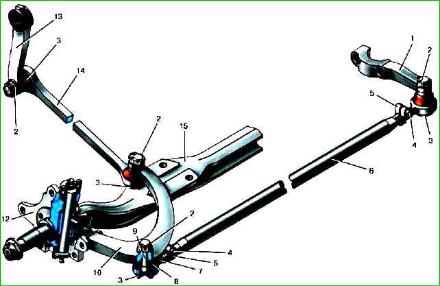
Beam 15 of the front suspension is stamped, I-section, connected to the steering knuckles using pins
The pins have a flat in the center and are locked in the beam holes with wedge pins.
Vertical loads from the steering knuckles are transmitted to the beam by thrust ball bearings, protected from dirt and dust by protective rubber-metal caps.
In the upper bosses of the steering knuckles, on the beam side, there are annular grooves in which rubber sealing rings are installed, protecting the friction surfaces of the bushings and pins from dust and dirt.
The pivot holes in the steering knuckle bosses are covered with covers with gaskets.
To lubricate the pin bushings, grease nipples are installed in the center of the covers.
The thrust bearings of the pins are lubricated simultaneously with the lubrication of the lower bushings.
There are special grooves for the passage of lubricant in the bushings of the steering knuckles.
The steering knuckles consist of two parts - a flange and a pin pressed into it.
The front wheel hubs with brake discs are mounted on axles on two tapered bearings.
The steering linkage is located behind the front axle beam.
The trapezoid arms are secured to the steering knuckles with high-strength bolts.
To eliminate the possibility of the bolts loosening during operation, the threaded parts of the connections during assembly are coated with Unigerm-6 sealant TU 6-01-1285-84.
Limitation of the steering wheel angles is ensured by bolts screwed into the steering knuckle flange.
Tie rod 14 - solid forged, transverse 6 - tubular, with threaded ends.
Threaded tips 7 have different thread directions, which allows you to adjust the toe-in of the wheels without removing traction from the car.
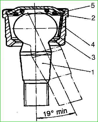
The longitudinal and transverse thrust joints (Fig. 2) are unified with each other.
The hinges are non-separable and do not require maintenance during operation.
Maintenance of the front suspension beam is described in the article - "Maintenance of the beam"
")

")
")
")
")
")
")
")