Electrical equipment is made according to a single-wire circuit: the negative terminals of sources and consumers of electricity are connected to the “ground” - the body and main components of the car, which serve as the second wire
The on-board network is DC, with a rated voltage of 12V.
When the engine is not running, all consumers are powered from the battery, and after starting the engine - from an alternating current generator with a built-in rectifier and voltage regulator.
When the generator is running, the battery is charged.
Carry out any work on the vehicle’s electrical equipment only with the battery disconnected.
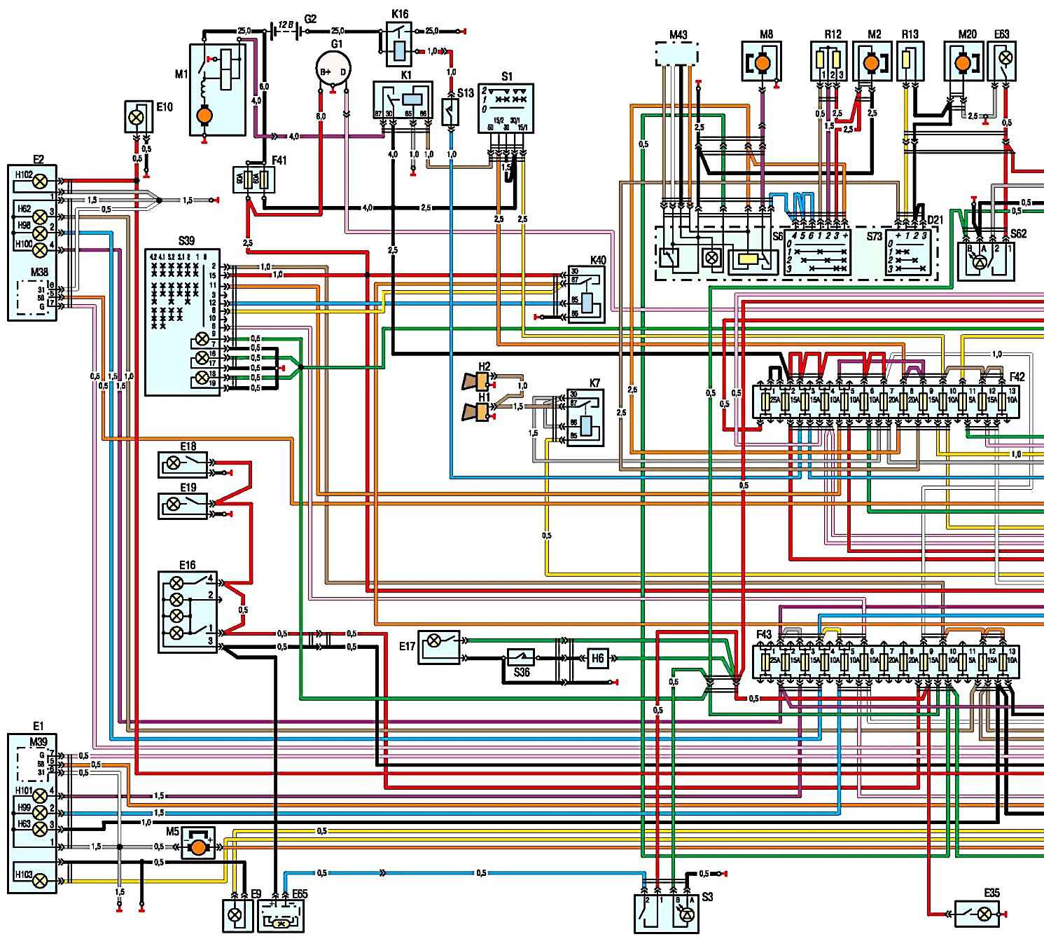
Fig. 1. Part one. SUD diagram for ZMZ-405 engine: A9 - fuel module; B1 - oil pressure indicator sensor; B2 - warning lamp sensor for emergency drop in oil pressure; B5 - warning lamp sensor for emergency drop in brake fluid level; B7 - coolant temperature indicator sensor; B8 - coolant overheat warning lamp sensor; B12 - fuel level indicator sensor; B13 - fuel level indicator sensor in the right tank (GAZ-33027); B17 - accelerator pedal position sensor; B46 - speed sensor; B57 - sensor for turning on the electromagnetic fan clutch; B64, B70 - temperature sensors; B72 - oxygen concentration sensor (for cars with an exhaust gas converter); B74 - synchronization and crankshaft speed sensor; B75 - mass air flow sensor; B76 - throttle position sensor (electronic throttle unit of the ZMZ-40524 engine); B91 - phase sensor; B92 - knock sensor; B97 - rough road sensor; D7 - anti-lock brake system control unit (installed on some cars); D21 - heating and ventilation unit control panel; D23 - engine control unit; D27 - instrument dimmer; E1 - left headlight; E2 - right headlight; E9 - left side turn signal; E10 - right side turn signal; E16 - courtesy lamp for the front seats of the cab; E17 - cargo platform lighting lamp (GA3-3302, -33021, -33027); E18, E19 - lampshades for lighting the cargo compartment of vans; E20 - passenger compartment lighting lamps (right); E27 - left rear lamp; E28 - rear right lamp; EZ0, E64 - license plate lights; E35 - engine compartment light; E59 - cigarette lighter; E60, E61 - passenger compartment lighting lamps (left); E63 - footrest lamp; E65 - courtesy light for the second row of seats (for vans with two rows of seats); E71 - glove box lighting;
The battery can only be disconnected or connected with the ignition off.
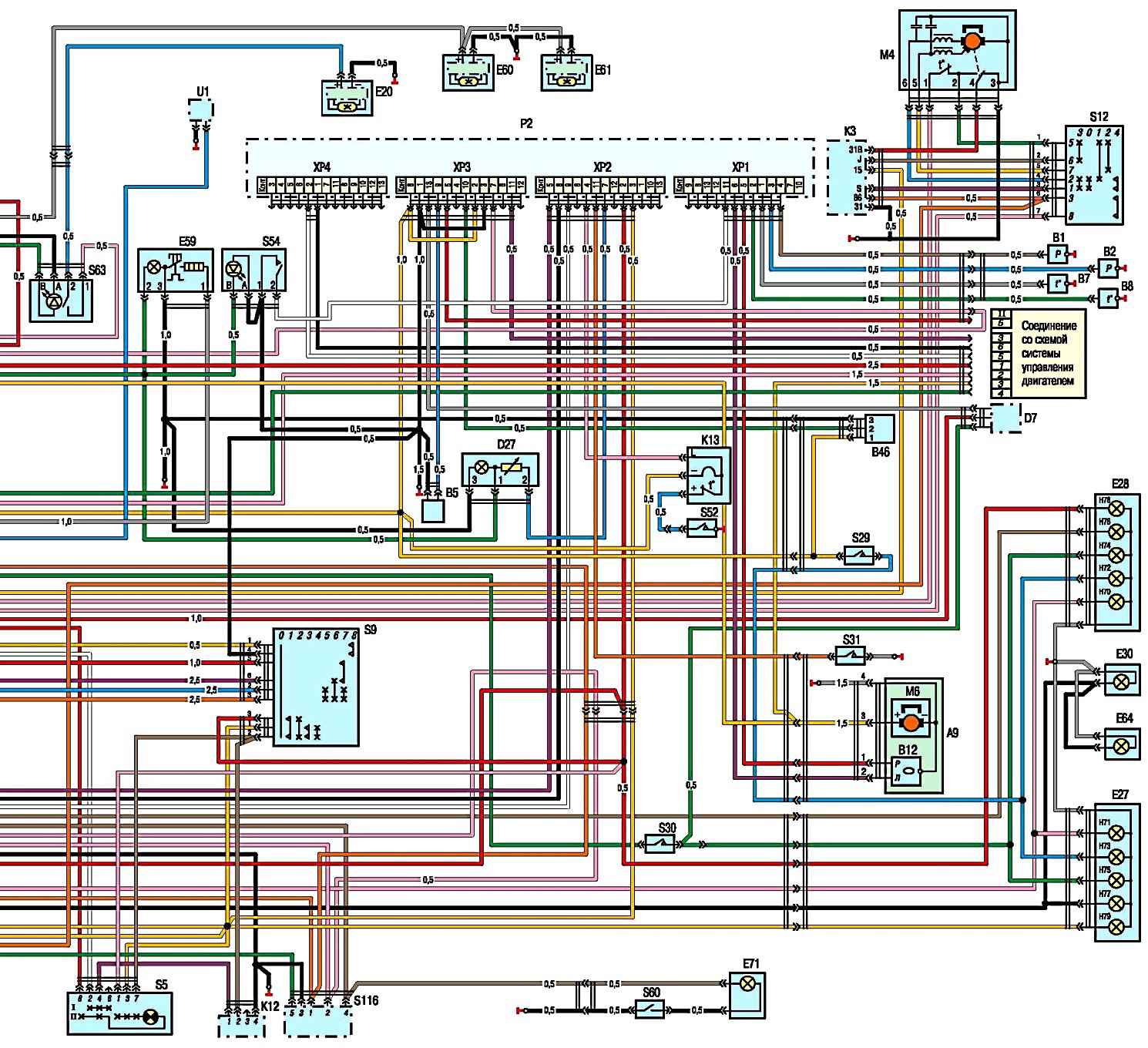
Fig. 2. Part two. Diagram of GAZ-3302, 2705 with ZMZ-405 engine: F1-F4 - spark plugs; F41 - additional fuse block; F42 - upper fuse box; F43 - lower fuse box; G1 - generator; G2 - battery; H1, H2 - sound signals; H6 - driver signal buzzer (GAZ-3302, -33021, -33027); H62 - left side light lamp; Н6З - right side lamp; H70 - rear left fog lamp; H71 - rear right fog lamp; H72 - left reversing lamp; H73 - right reversing lamp; H74 - left brake light lamp; H75 - right brake light lamp; H76 - left tail light lamp; H77 - right tail light lamp; H78 - left rear turn signal lamp; H79 - right rear turn signal lamp; H98 - left low beam lamp; I99 - right low beam lamp; H100 - left high beam lamp; H101 - right high beam lamp; H102 - left front turn signal lamp; H103 - right front turn signal lamp; K1 - starter relay; K3 - windshield wiper control relay; K7 - signal relay; K9, K46 - relay; K12 - turn signal switch; K13 - breaker for the parking brake warning light; K16 - remote battery switch (for buses); K36 - relay for turning on the electromagnetic clutch; K40 - headlight switch relay; M1 - starter; M2 - heater fan electric motor; M4 - windshield wiper motor; M5 - electric motor of the windshield washer pump; M8 - electric pump for additional heater (for buses and vans with two rows of seats); M10 - electric fuel pump; M20 - electric motor for additional heater (for buses and vans with two rows of seats); M38 - electric drive for headlight range control (right); M39 - electric drive for headlight range control (left); M43 - heater valve gearmotor; P2 - instrument cluster; R12 - heater motor resistor; R13 - resistor of the auxiliary heater electric motor (for buses and vans with two rows of seats); S1 - switch for the starting system and instruments; S3 - lamp switch for the second row of seats (for vans with two rows of seats); S5 - alarm switch; S6 - switch for electric motor and electric heater pump; S9 - switch for direction indicators and headlights; S12 - wiper switch; S13 - push-button switch for remote battery switch (for buses); S14 - fuel level sensor switch (GAZ-33027); S29 - reverse light switch; S30 - brake light switch; S31 - switch for the center differential lock warning light (for vehicles with a 4x4 wheel arrangement); S36 - driver signal switch (GAZ-3302, -33021, -33027); S39 - light switch; S52 - parking brake warning lamp switch; S54 - switch for checking the serviceability of signal lamps; S60 - glove compartment lamp switch; S62 - switch for the right lamps for lighting the passenger compartment of buses; S63 - switch for the left lamps for lighting the passenger compartment of buses; S73 - switch for the electric motor of the additional heater (for buses and vans with two rows of seats); S116 - headlight range control switch; T1-T4 - ignition coils; U1 - radio receiver; X38, X51 - socket pads; X53 - pin block; Y19-Y22 - electromagnetic injectors; Y23 - idle speed regulator; Y46 - canister purge valve (for vehicles with a fuel vapor recovery system); Y48 - electromagnetic clutch for shutting off the engine cooling system fan; (I) - turning on the rear lights of vans and buses; (II) - chassis option; (III) - option with two fuel tanks; I - pin numbers
When checking electrical equipment circuits, it is prohibited to short-circuit the wires to ground (check the serviceability of the circuits for a spark), as this can lead to failure of electrical equipment elements.
It is prohibited to use fuses that are not provided for by the design of the vehicle or are designed for a higher current, as well as use wire instead of fuses.
When replacing fuses, do not use screwdrivers or metal tools, as this can lead to a short circuit in the electrical circuits.
It is forbidden to disconnect the battery while the engine is running, as this will lead to failure of the voltage regulator and elements of the vehicle's electronic equipment.
To avoid failure of the diodes of the rectifier unit, it is prohibited to check them with a megger or a test lamp supplied with a voltage of more than 12 V, as well as to check the electrical circuits on a car with such devices without disconnecting the wires from the generator.
It is necessary to check the insulation resistance of the generator stator winding with increased voltage on the generator removed from the vehicle, with the stator winding terminals disconnected from the rectifier unit.
When carrying out electrical welding work on a car, it is necessary to disconnect the wires from the terminals of the battery and generator.
Do not touch the ignition system components and high-voltage wires while the engine is running.
It is prohibited to check the functionality of the ignition system “for a spark” between the tips of high-voltage wires and the “ground”, as this will lead to failure of elements of electronic equipment.
Do not lay low voltage wires in the same bundle as high voltage wires.
Regularly clean the battery terminals and wire tips from oxides and dirt.
When recharging the battery using a charger, disconnect the wires from the battery terminals.
")

")
")
")
")
")
")
")