car ZIL-131
The ZIL-131 is the base model in a family of three-axle, all-terrain, multipurpose vehicles with all-wheel drive. The wheel arrangement is 6x6. The vehicle is equipped with an eight-cylinder, V-shaped, carbureted engine producing 150 hp. All electrical components are shielded. The clutch is single-disc, and the transmission is five-speed with two synchronizers for second-third and fourth-fifth gears. Fifth gear is direct. The transfer case is a two-shaft unit with upshift, downshift, and neutral gears. Torque in the transfer case is transmitted to driveshafts, one of which connects the transfer case to the front axle, the other to the middle axle, and through it to the rear axle.
The front axle has independent suspension, and the two rear axles are suspended on a balance beam bogie with a single pair of springs.
The steering is equipped with a hydraulic booster, integrated into the steering gear.
The vehicle is equipped with a three-seat all-metal cab and a wooden platform with metal fittings and metal crossbars. The platform's side extensions form folding benches, and an additional bench can be installed in the middle of the platform.
The vehicle's load capacity when operating on mixed roads with various surfaces, including off-road conditions, is 3.5 tons, and on paved roads in good condition, it is 5 tons.
The towable trailer weight on mixed roads is 4 tons, and on paved roads, 6.5 tons.
The vehicle is equipped with 12.00-20 tires with centralized air pressure control.
For improved off-road performance, the vehicle is equipped with a winch. It can ford water up to 1.4 meters deep.
The ZIL-131A is a modification of the ZIL-131, differing from the base model in that it has unshielded electrical equipment.
The ZIL-131V is a semi-trailer truck based on the ZIL-131 and designed to tow a special semi-trailer.
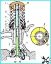
The steel camshaft with hardened cams and distributor drive gear is driven by two gears
Symptom - Remedy
The generator does not provide charging current
Malfunction in the circuit generator - relay-regulator - battery or in the ground circuit - Find damage in the wiring or contacts and eliminate it:
")

")
")
")
")
")
")
")