Most of the vehicle's electrical circuits are protected by fuses
Electric motors of gear motors (windshield wipers, rear door glass, headlights - if installed) are protected by automatic bimetallic reusable fuses
The power supply circuit of the injection system (VAZ-21214 engine) is protected by a fuse made of a wire with a core of reduced cross-section (1 mm 2 ).
The circuits for charging the battery, ignition (VAZ-21213 engine), engine start, and the "generator - ignition switch - fuse box" circuit are not protected.
Powerful consumers (starter, headlights, electric motors of cooling system fans, electric fuel pump, etc.) are connected via a relay.
The fuses are grouped in two fuse boxes located on the left under the instrument panel.
The fuse ratings and the circuits they protect are shown in the table.
The injection system fuses (VAZ-21214 engine) are located in a separate block on the left side panel under the instrument panel.
A 30 A fuse protects the power supply circuit of the radiator electric fans, and three 15 A fuses protect the electric fuel pump, control unit (constant power input) and the main relay circuits of the injection system, respectively.
Replacing fuses, removing the fuse box
Disconnect the "negative" wire from the battery.
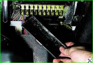
Pull the latch located on top of the main fuse box cover to remove the cover.
Remove the cover of the additional fuse box in the same way.
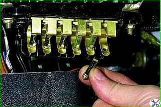
Replacing fuse.
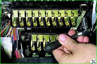
To remove the fuse boxes, use an "8" head to unscrew the two nuts
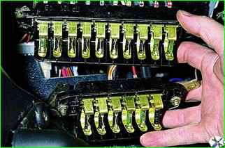
Remove the main and additional blocks from the studs.
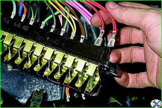
Before replacing the fuse boxes, mark the wires and disconnect them
Install new fuse boxes in the reverse order
Removing the relay box
To the right of the steering column, under the instrument panel, there is a block of three identical relays of the 113.3747-10 type, controlling the switching on of: low beam headlights, high beam headlights and heating of the rear door glass.
Disconnect the negative wire from the battery.
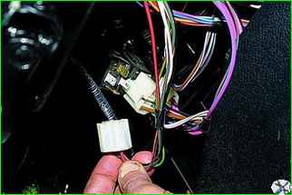
To remove the relay, disconnect the socket.
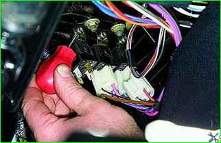
After unscrewing the screw with a Phillips screwdriver,…
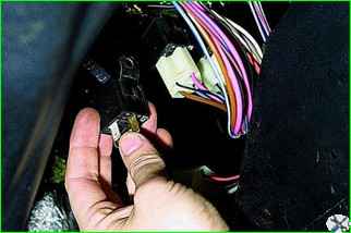
Removing the relay.
The starter and ignition relays are secured under the additional fuse box (on a car with an injection engine, they are attached to the injection system relay bracket).
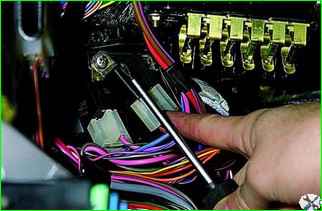
Using a Phillips screwdriver, unscrew the screw securing both relays
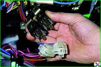
After removing the relay, disconnect the pads
Install the relays in the reverse order
Since all the relays are of the same type, if one of them fails, you can temporarily connect its pad to another relay.
For example, if the starter relay fails, its pad can be connected to the rear door glass heating relay.
Replacing the injection engine control system fuses
Disconnect the negative battery cable.
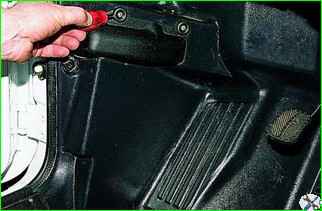
To access the fuses and diagnostic connector of the engine management system, use a Phillips screwdriver to unscrew the two screws in the passenger compartment that secure the casing to the trim of the front left side of the body.
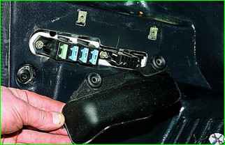
Remove the casing.
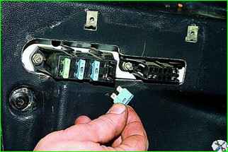
Remove the fuse.
The fuse of the electric fans circuit, located on the block at the back, has a rating of 30 A (green), three other fuses with a rating of 15 A (blue) protect the circuits of the main relay, controller power supply and fuel pump.
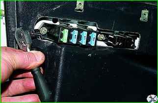
To remove the fuse box, use the head "on the 8" unscrew the two nuts securing the unit and remove it.
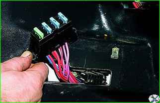
Install the fuse box in the reverse order
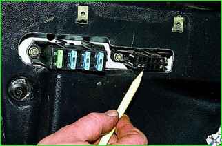
Next to the fuse box is the diagnostic connector
Circuits protected by fuses
Fuse No. Protected circuits (current)
1 (16 A):
- - Heater fan motor. Headlight wiper relay (winding) and headlight wiper motors for all brush positions except the initial one.
- - Relay (winding) for switching on the rear door glass heating.
- - Rear door glass wiper and washer motors.
- - Windshield washer motor
2 (8 A):
- - Windshield wiper relay and motor.
- - Direction indicator lamps and flasher relay for direction indicators and hazard warning lights (in direction indicator mode).
- - Direction indicator lamp. Rear lights (reversing lights).
- - Generator excitation winding (when starting the engine) and battery charge indicator light*.
- - Differential lock indicator light. Parking brake system interrupter relay and indicator light.
- - Low brake fluid indicator light. Oil pressure indicator light. Coolant temperature gauge.
- - Fuel gauge with reserve indicator light. Tachometer 3 (8 A) Left headlight (high beam). Headlight high beam indicator lamp
4 (8 A):
- Right headlight (high beam)
5 (8 A):
- Left headlight (low beam)
6 (8 A):
- Right headlight (low beam)
7 (8 A):
- - Left front light (parking light).
- - Right rear light (parking light).
- - License plate lights.
- - Parking light indicator lamp
8 (8 A):
- - Right front light (parking light).
- - Left rear light (parking light). light).
- - Instrument cluster illumination lamps.
- - Heater control lever illumination panel.
- - Cigarette lighter illumination lamps.
- - Switch illumination lamps
9 (16 A):
- - Direction indicators and flasher relay for direction indicators and hazard warning lights in hazard warning mode.
- - Rear window heating element and relay (contacts) for switching it on.
10 (16 A):
- - Horn.
- - Socket for portable lamp.
- - Interior lights.
- - Tail lights (brake lights)
13 (8 A):
- - Tail lights (fog lights).
- - Headlamp wiper motors at start-up and when the wipers pass their initial position.
- - Headlight washer relay (contacts).
- - Headlight washer motor
15 (16 A):
- Cigarette lighter
* On cars manufactured before 1996, a voltmeter was installed in the instrument cluster instead of a control lamp, which was also protected by fuse No. 2.


