Rear suspension — dependent, with coil springs and double-acting hydraulic telescopic shock absorbers
All suspension elements are attached to brackets on the rear axle beam.
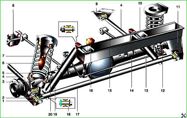
Rear suspension elements: 1 — rubber bushing; 2 — spacer bushing; 3 — lower spring insulating gasket; 4 — lower longitudinal rod; 5 — lower spring support cup; 6 - compression buffer; 7 - suspension spring; 8 - upper longitudinal rod mounting bolt; 9 - lower longitudinal rod mounting bracket; 10 - body floor cross member; 11 - cross rod bracket; 12 - rear brake pressure regulator; 13 - pressure regulator drive lever; 14 - rear axle beam; 15 - upper longitudinal rod; 16 - additional compression buffer; 17 - cross rod; 18 - shock absorber eye rubber bushing; 19 - shock absorber; 20 – spring insulating gasket
The two lower longitudinal rods prevent the longitudinal movement of the beam, the two upper ones prevent the beam from twisting around the axis under the action of traction and braking forces on the rear wheels.
The transverse rod ("Panhard rod") limits the beam's displacement in the transverse direction.
The other ends of the rod are attached to brackets on the car body.
Rubber-metal hinges are pressed into the eyes at the ends of the rods.
They can be replaced separately, provided that the eyes themselves are not worn out.
Deformed rods can be straightened.
The rod mounting bolts can only be tightened in the "car on wheels" position, while the distance from the bridge beam to the side member above it should be 152 mm.
The shock absorbers are attached with their lower part to the brackets on the rear axle beam, and with their upper part to the pins on the body floor crossmember through rubber cushions with spacer bushings and washers.
The shock absorber mounting bolts can only be tightened in the "car on wheels" position.
The suspension spring rests on the lower and upper cups.
The plastic gasket is installed in the lower support cup welded to the rear axle beam.
The upper end of the spring rests through a rubber gasket on the upper support cup welded to the body.
The compression buffer bracket is also welded to it.
At maximum suspension travel, the rubber buffer rests against the lower support cup of the spring.
When replacing springs, make sure that they are the same class (class (A) - without markings, class (B) - with a black stripe on the outer surface of the coils, has a shorter length under load).
It is permissible to install class (A) springs on the front suspension and class (B) on the rear, but not vice versa.
")

")
")
")
")
")
")
")