Cooling system – liquid, closed type, with forced circulation
The tightness of the system is ensured by valves in the expansion tank plug.
The inlet valve is normally open (the gap between it and the rubber gasket is 0.5–1.1 mm) - in this case, the system communicates with the expansion tank.
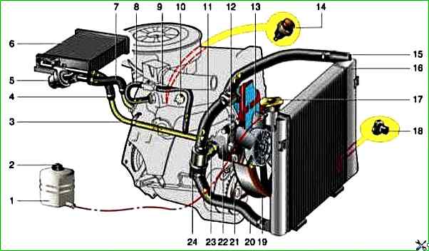
Cooling system BA3-21213: 1 - expansion tank; 2 - expansion tank plug; 3 - pipe for draining fluid from the heater radiator; 4 - hose for draining fluid from the heater radiator; 5 - heater tap; 6 - heater radiator; 7 - hose for supplying fluid to the heater radiator; 8 - hose for supplying fluid to the carburetor heating block; 9 - hose for draining fluid from the carburetor heating unit; 10 - thermal vacuum switch of the recirculation valve; 11 - thermostat bypass hose; 12 - coolant pump cover; 13 - fan impeller; 14 - coolant temperature sensor for the instrument cluster; 15 - radiator supply hose; 16 - radiator; 17 - radiator cap; 18 - radiator drain plug; 19 - fan casing; 20 - radiator outlet hose; 21 - coolant pump drive belt; 22 - coolant pump housing; 23 - hose for supplying coolant to the pump; 24 - thermostat
When the engine heats up, the liquid expands and is forced into the tank; when it cools, it returns back.
The inlet valve closes when the pressure in the system sharply increases (liquid boils), while the outlet valve is also closed.
It opens when the pressure in the system reaches approximately 0.5 kgf/cm 2, which increases the boiling point of the liquid and reduces its losses.
Thermal operation of the engine is maintained by a thermostat and radiator fan.
On a carburetor engine, the fan is mechanically driven, mounted on the coolant pump pulley.
On an engine equipped with an injection system, two electric fans are installed in front of the radiator and are activated by command from the electronic engine control unit.
The coolant pump is a vane, centrifugal type, driven from the crankshaft pulley by a V-belt.
Pump housing is aluminum.
The roller rotates in a double-row bearing with a lifetime supply of lubricant.
The outer ring of the bearing is locked with a screw.
A pulley hub is pressed onto the front end of the roller, and a plastic impeller is pressed onto the rear end.
For the correct position of the pump pulley groove, the distance from the mating surface of the pump cover to the outer end of the hub must be 84.4±0.1 mm.
When installing the cover with gasket, check the gap of 0.9–1.3 mm between the impeller blades and the pump housing.
To do this, you can use plasticine rollers: they are placed on equidistant impeller blades, the cover is installed, the nuts securing it are tightened, then the cover is removed and the remaining thickness of the plasticine is measured - it is equal to the gap.
Axial and radial play in the pump bearing that can be felt by hand is not allowed.
If the pump bearing or self-clamping oil seal fails, it is recommended to replace the pump cover complete with the roller and impeller.
The redistribution of liquid flows is controlled by a thermostat with a solid heat-sensitive element.
On a cold engine, the thermostat valve closes the pipe leading to the radiator, and the liquid circulates only in a small circle (through the thermostat bypass pipe), bypassing the radiator.
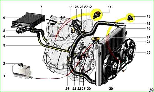
Cooling system VAZ-21214: 1 - expansion tank; 2 - expansion tank plug; 3 - pipe for draining fluid from the heater radiator; 4 - hose for draining fluid from the heater radiator; 5 - heater tap; 6 - heater radiator; 7 - hose for supplying fluid to the heater radiator; 8 - hose for supplying fluid to the carburetor heating block; 9 - hose for draining fluid from the carburetor heating unit; 10 - thermal vacuum switch of the recirculation valve; 11 - thermostat bypass hose; 12 - coolant pump cover; 13 - fan impeller; 14 - coolant temperature sensor for the instrument cluster; 15 - radiator supply hose; 16 - radiator; 17 - radiator cap; 18 - radiator drain plug; 19 - fan casing; 20 - radiator outlet hose; 21 - coolant pump drive belt; 22 - coolant pump housing; 23 - hose for supplying coolant to the pump; 24 - thermostat; 25 - coolant supply hose to the throttle body; 26 - hose coolant drainage from the throttle body; 27 - coolant temperature sensor for the injection system; 28 - electric fan impeller; 29 - electric motor; 30 - electric fan casing
The small circle includes the heater radiator, intake manifold, carburetor heating unit (on engine 21213) or throttle assembly (on engine 21214).
At a temperature of 78–85°, the valve begins to move, opening the main pipe; in this case, part of the liquid circulates in a large circle through the radiator.
At a temperature of about 90°, the main valve opens completely, and the bypass valve closes, and all the liquid circulates through the engine radiator.
The stroke of the main valve must be at least 6.0 mm.
You can evaluate the health of the thermostat by heating the lower radiator pipe: it should be cold until the fluid temperature (according to the indicator) reaches 80–85°, and hot when it rises to 85–90°.
The thermostat cannot be repaired.
If there is a malfunction, loss of tightness, or deformation of the pipes, it is replaced.
The radiator consists of two vertical plastic tanks (the left one has a baffle) and two horizontal rows of round aluminum tubes with pressed-on cooling plates.
To increase cooling efficiency, the plates are stamped with a notch. The tubes are connected to the tanks through a rubber gasket.
The liquid is supplied through the upper pipe and discharged through the lower one.
At the bottom of the left tank there is a plug for draining the coolant.
For better radiator airflow, casings are designed to direct air flow from the fan(s).
On the 21213 engine, the main fan casing consists of two halves (lower and upper), the lower half has a rubber seal on the radiator side.
An additional guide casing is installed in front of the radiator.
On the 21214 engine, electric fans rotate in a casing in front of the radiator.
The expansion tank is made of translucent polyethylene, which allows you to visually monitor the fluid level (3–5 cm above the “MIN” mark on a cold engine).
To monitor the coolant temperature, a sensor is screwed into the engine cylinder head, connected to the temperature gauge on the dashboard.
An additional temperature sensor is installed in the exhaust pipe of the 21214 engine, which provides information to the electronic engine control unit.
The cooling system is filled with 10.7 liters of coolant with a freezing point of no higher than -40°.
Replacing the coolant
We carry out the work on a cold engine.
Open the heater tap.
Unscrew the radiator cap.
We place the container and prepare a hose with an internal diameter of 16 mm.

Unscrew the cap in the lower left corner of the radiator and drain the liquid from the radiator through the hose.

To drain the fluid from the engine, use a 13mm spanner to unscrew the plug on the left side of the cylinder block and drain the fluid by pressing the same hose against the hole in the block
To drain the expansion tank, disconnect its fastening.
Open the cap and, lifting the tank, drain the coolant through the radiator.
We close the drain plugs and return the expansion tank to its place.
Fill coolant through the radiator to the upper edge of the filler neck.
Fill the liquid into the expansion tank to a level 3-4 cm above the MIN mark.
Start the engine, add fluid.
We warm up the engine with the radiator cap closed.
After the coolant has cooled, check its level. Top up if necessary.
")

")
")
")
")
")
")
")