car UAZ-3151
The UAZ-3151, -31512, -31514, and -31519 are two-axle, all-wheel-drive, cargo-passenger vehicles with an all-metal bonnet-type body mounted on a frame. The body is available with a hardtop or soft (canvas) top.
The vehicle seats seven, including the driver, with the two rear passengers facing each other on folding seats.
When the rear seats are folded, a cargo compartment is created in the rear.
The UAZ-3151 can seat from four to eight passengers, depending on the number and arrangement of the seats.
The gasoline engine, a four-cylinder in-line engine with a displacement of 2.445 or 2.89 liters, is mounted longitudinally in the front of the vehicle.
The vehicle's transmission features a disconnectable front axle and a downshifting gear in the transfer case. The front axle is equipped with clutches that disconnect the drive from the wheels.
The axles can be equipped with additional wheel reduction gears, which increases ground clearance from 220 to 300 mm.
The vehicles are equipped with stamped steel wheels with a 15- or 16-inch rim diameter and all-terrain tires.
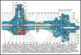
In the article we will consider possible malfunctions of the rear axle of the UAZ-3151
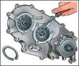
Assemble the transfer case from a subassembly of its components
")

")
")
")
")
")
")
")